Quadra-polar modulator

a modulator and quadratic polar technology, applied in the field of quadratic polar modulators, can solve the problems of poor noise and power performance of the architecture, and the need for complex pre-processing of the i and q modulating signals of the linc architecture, and achieve the effect of simple implementation and good noise performan

Active Publication Date: 2006-01-03
QUALCOMM INC
View PDF4 Cites 15 Cited by
  • Summary
  • Abstract
  • Description
  • Claims
  • Application Information

AI Technical Summary

Benefits of technology

[0007]A quadra-polar modulator is provided herein having key advantages from both the QAM and polar modulators. In particular, the quadra-polar modulator is simple to implement since it can accept the I and

Problems solved by technology

However, this architecture may suffer from poor noise and power performance.
The LINC architecture also requir

Method used


Image

  • Quadra-polar modulator
  • Quadra-polar modulator
  • Quadra-polar modulator

Examples


Embodiment Construction

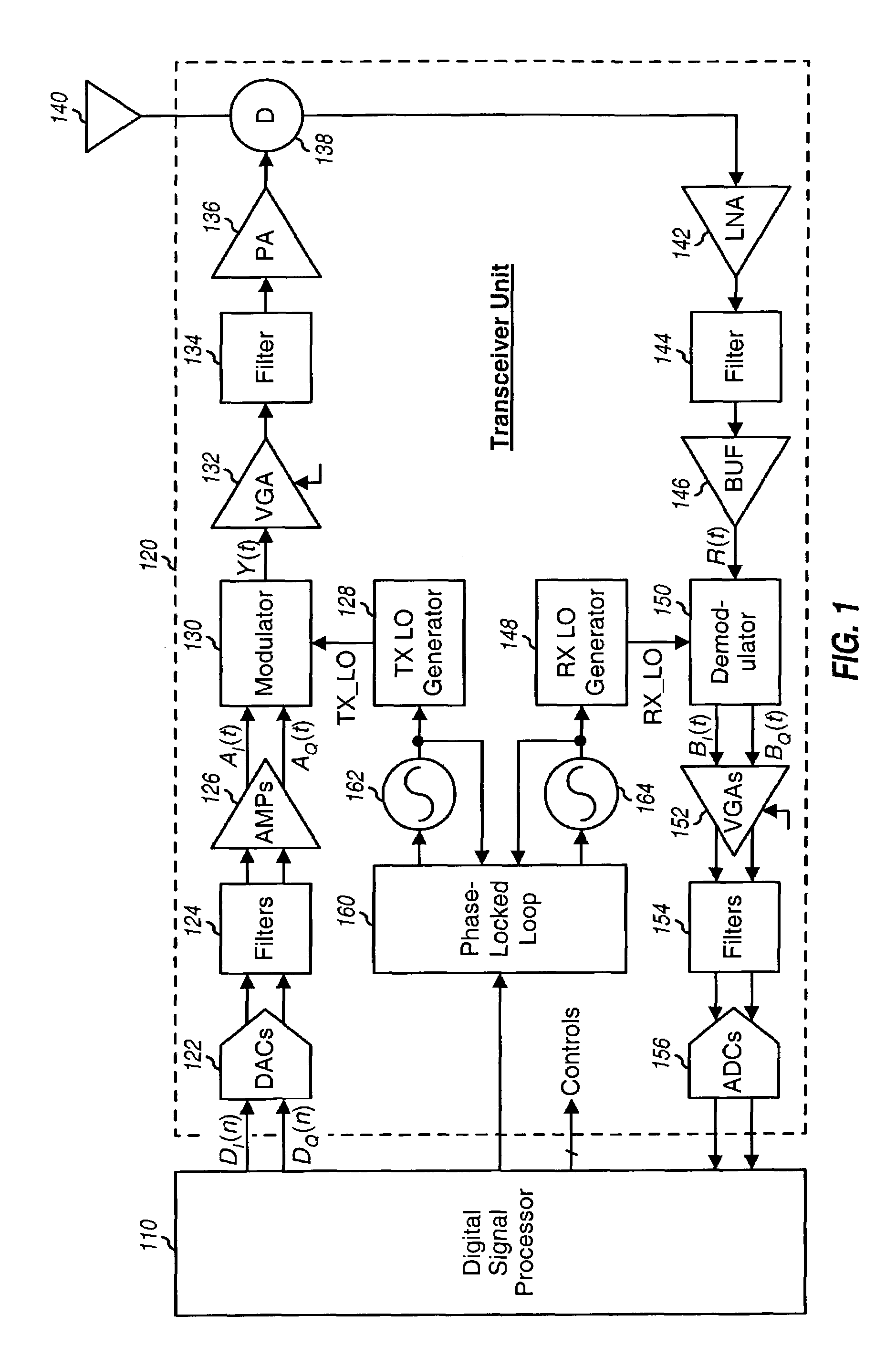
[0018]FIG. 1 shows a block diagram of an embodiment of a transceiver unit 120 that may be used for wireless communication. Transceiver unit 120 includes a transmitter for data transmission and a receiver for data reception. Transceiver unit 120 may be used in a terminal (e.g., a cellular phone or handset) or a base station in a CDMA system, and may also be used in other devices for other communication systems.

[0019]In the transmit path, a digital signal processor (DSP) 110 provides traffic data as I and Q data streams, which are denoted as DI(n) and DQ(n). The I and Q data streams are converted to I and Q analog signals by digital-to-analog converters (DACs) 122, filtered by filters 124 to remove images caused by the digital-to-analog conversion, and amplified by amplifiers (AMPs) 126 to provide I and Q modulating signals, which are denoted as AI(t) and AQ(t).

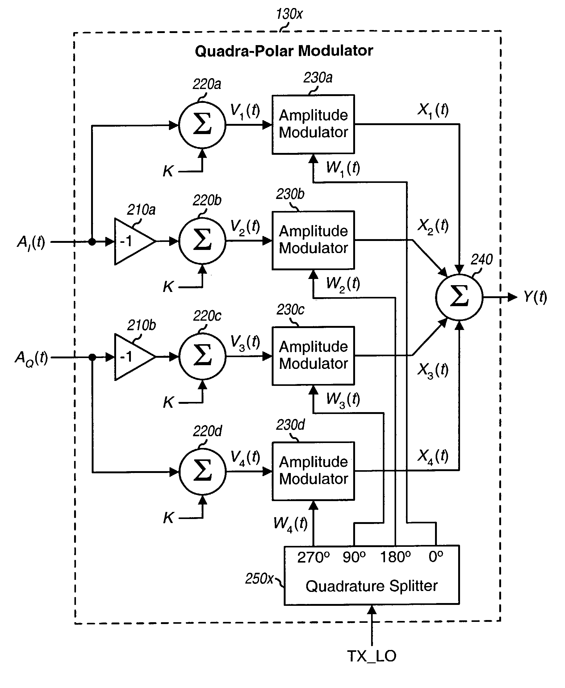
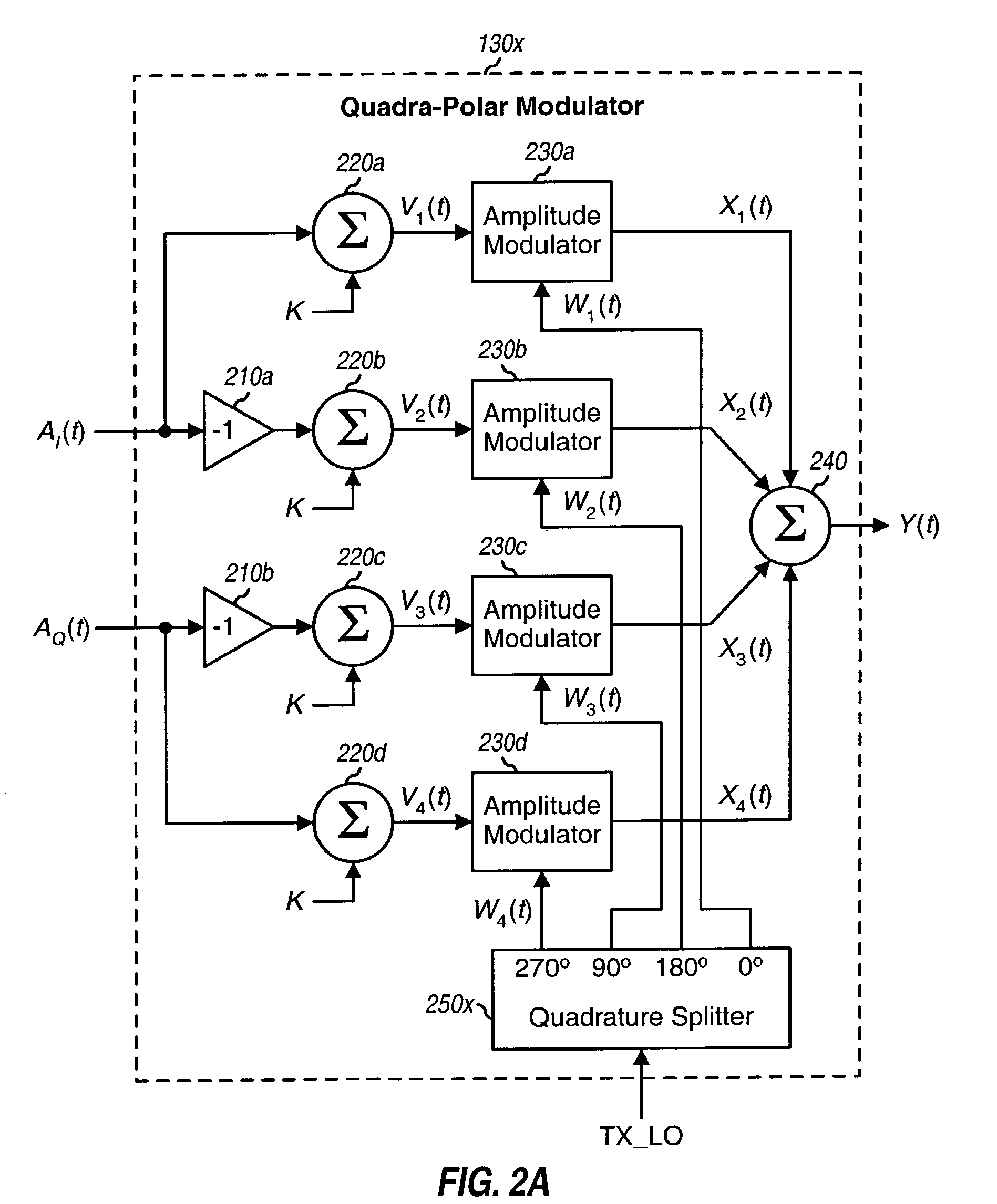
[0020]A modulator 130 receives the I and Q modulating signals from amplifiers 126 and a TX—LO signal from a transmit (TX) loc...


PUM


Abstract

A quadra-polar modulator that is simple to implement and also provides good noise performance. The quadra-polar modulator includes four amplitude modulators and a combiner. Each amplitude modulator modulates a respective carrier signal with a respective input signal to provide a respective output signal. The combiner then combines the four output signals from the four amplitude modulators to provide a modulated signal. Each amplitude modulator may be implemented with a switching amplifier, such as a supply modulated class E amplifier. Two input signals are obtained by summing separately an inphase (I) modulating signal and an inverted I modulating signal with an offset value. The other two input signals are obtained by summing separately a quadrature (Q) modulating signal and an inverted Q modulating signal with the offset value. The offset value can be selected based on the expected magnitude of the modulating signals. The four carrier signals are in quadrature to each other.

Description

BACKGROUND[0001]I. Field[0002]The present invention relates generally to electronic circuits, and more specifically to a quadra-polar modulator for use in communication systems.[0003]II. Background[0004]In a typical communication system, traffic data is first processed digitally to obtain coded data. The coded data is then used to modulate a carrier signal to obtain a modulated signal that is more suitable for transmission over a communication link. Modulation may be broadly defined as a process whereby one or more characteristics of a carrier signal are varied in accordance with a modulating wave (see also, IEEE Standard Dictionary of Electrical and Electronic Terms). The carrier signal is typically a periodic signal (e.g., a sinusoidal signal) of a particular frequency. The modulating wave may be derived from the coded data and may be provided as an inphase (I) modulating signal and a quadrature (Q) modulating signal. Typically, the amplitude and / or the phase of the carrier signal...

Claims


Application Information

Patent Timeline
IPC IPC(8): H04L5/12H03C1/54H04L27/36
CPCH03C1/547H03F3/2176H04L27/362
Inventor BALLANTYNE, GARY J.
Owner QUALCOMM INC
Why Eureka
Try Eureka