Acoustical panel having a honeycomb structure and method of making the same

a honeycomb structure and acoustic panel technology, applied in the field of acoustic panels, can solve the problems of health and environmental concerns, use of fiberglass, and cost of fiberglass relative to natural fibers, and achieve the effects of improving the sound quality of the acoustic panel, improving the sound quality, and improving the sound quality

Inactive Publication Date: 2006-01-10
AWI LICENSING
View PDF38 Cites 54 Cited by
  • Summary
  • Abstract
  • Description
  • Claims
  • Application Information

AI Technical Summary

Problems solved by technology

However, there are many disadvantages associated with the use of fiberglass.
Disadvantages include the cost of the fiberglass relative to natural fibers, complexity and costs associated with manufacturing fiberglass acoustical panels with organic binders, health and environmental concerns associated with the use of organic solvents and organic binders in the manufacture of fiberglass acoustic panels, and the lack of strength associated with acoustic panels having inner cores comprised of fiberglass batts.
Unfortunately, wet-processed materials that exhibit sufficient stiffness and surface hardness are usually quite dense, have small and closed pores, and therefore do not display acceptable sound absorption characteristics.
Furthermore, wet-processed materials with highly acoustical absorbent properties are much less dense due to increased porosity, and therefore do not exhibit sufficient stiffness and surface hardness properties required for acoustic panel applications.
Additionally, since traditional wet-processing techniques require a vacuum drawn through a cross-section of the wet-laid material to remove water, a significant porosity size gradient arises through a cross-section of the panel, which further degrades the acoustic attenuation properties and strength of the finished panel.

Method used


Image

  • Acoustical panel having a honeycomb structure and method of making the same
  • Acoustical panel having a honeycomb structure and method of making the same

Examples


example 1

Formulation 4

[0034]

Front Cavity PercentageNRC (Scrim)NRC (Back) 0%0.660.7010%0.710.7217%0.670.7326%0.690.6937%0.680.6850%0.660.7070%0.640.71

[0035]Applicants believe that the data produced from Example 1 reveals little variation in acoustical values as related to the diameter or void volume of the cavity.

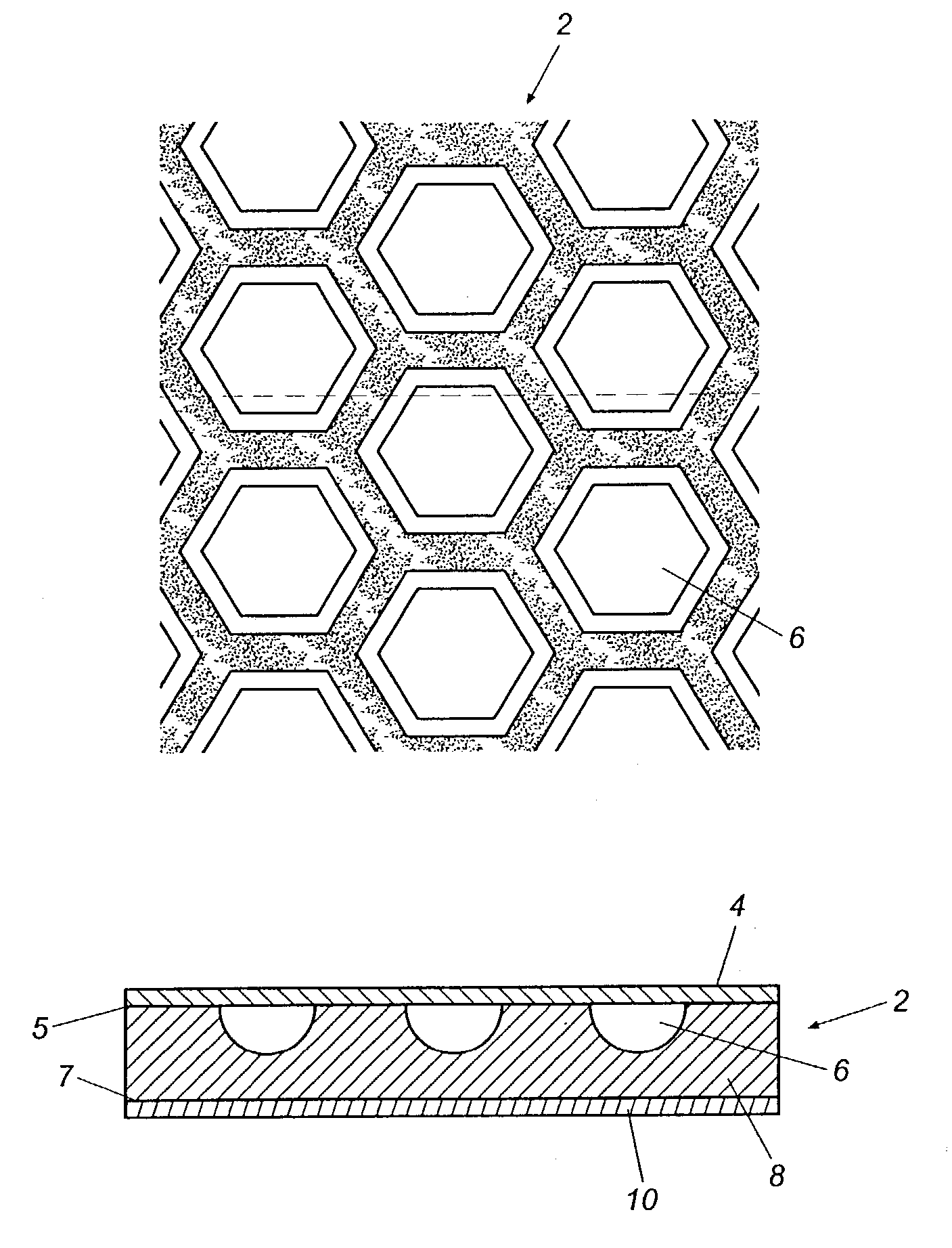
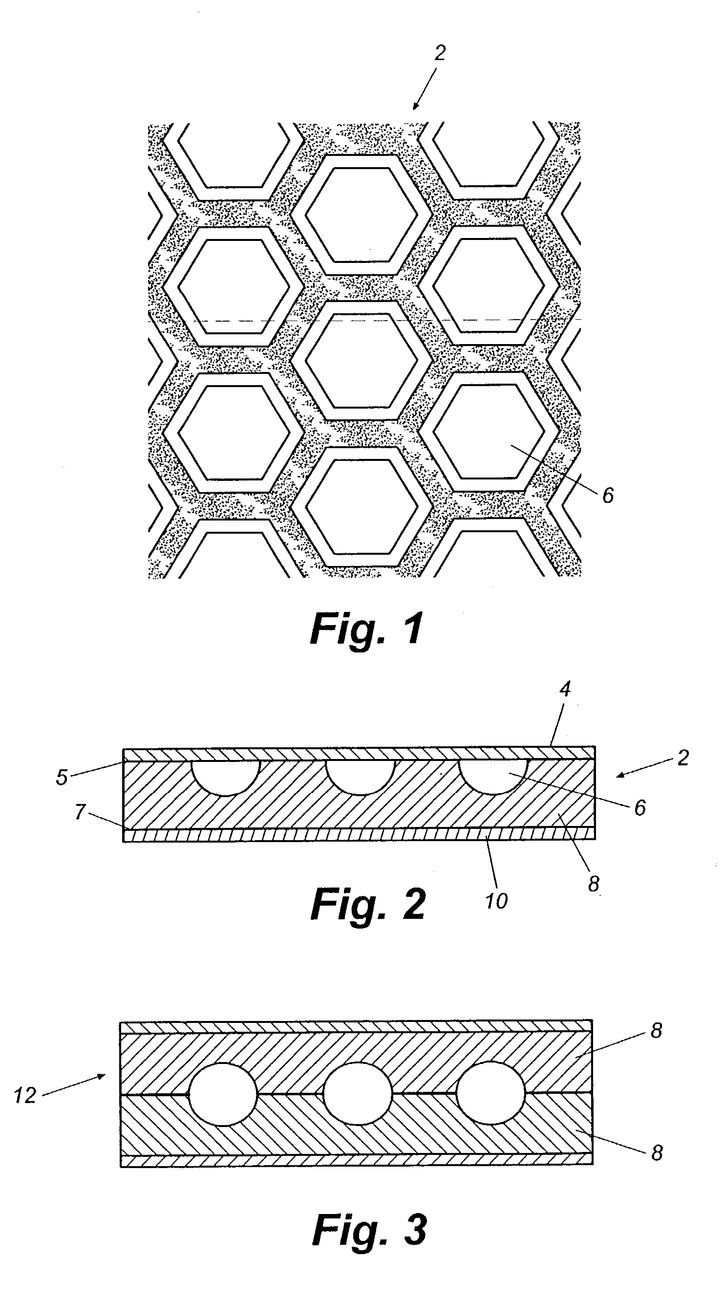
[0036]In Example 2, Applicants evaluated the overall effect of the thickness of the backing with regard to acoustic performance. In this Example, a ⅜ inch thick layer 8, having the various depressions 6, therein integral with the foamed, cementitious composition, having a thickness of 0 to ⅜ inch as measured from the bottom of the cell depressions to the planar first surface was varied. A fiberglass scrim was applied over the depressions on a first surface of layer 8. NRC values in the table below for Example 2 note whether the sound was directed at the scrim or at the planar backside of the gypsum foam. The data reveal some dependence of NRC on the direction from which the sound app...

example 2

Formulation 4

[0037]

Backing ThicknessScrimBack01.001.00 1 / 160.830.84 1 / 8 0.780.78 1 / 4 0.790.70 3 / 8 0.720.59

[0038]Example 3 below illustrates an additional test of the same material of Formulation 4 to confirm that the scrim covered honeycombed face is more acoustical than the continuous back face. For Example 3, Applicants utilized a reverberation room test that conforms to the following standards: ASTM C423-90a, E 122, E 548, E 795; ANSI S1.6, S1.26, S.1.11; and ISO R 354-1963. Applicants also conducted an airflow test that conforms to ASTM D 737 standards. Additionally, Applicants conducted Sound Transmission Coefficient (STC) tests having results determined by an insertion loss as set forth in ASTM E 90.

example 3

Formulation 4

[0039]

NRCAir Flow(reverb room)(ohms)STCHoneycombScrimBackScrimBackScrimBack30 lb / cuft0.480.382163435

[0040]Another property for examination was the density of the gypsum foam used for the layer 8. In Example 4, Applicants controlled the density to some extent by varying the amount of water added to the mixture. A greater weight percentage of water results in a lower density foam, when the foam is dried. All samples of the layer 8 were ⅝ of an inch thick, without depression 6. The relationship between the density and acoustical properties is most significant as demonstrated in the table for Example 4 below. The greatest acoustical absorbency occurs between the density ranges from 17 to 25 pounds per cubic feet.


PUM

PropertyMeasurementUnit
thicknessaaaaaaaaaa
thicknessaaaaaaaaaa
size distributionaaaaaaaaaa

Abstract

An acoustically absorbent porous panel with a layer constructed from a substantially continuous open-celled porous material comprising a cured foamed cementitious material including a first face and a second face. The first face has a surface with a substantially planar profile and the second face has a substantially geometric pattern of depressions formed therein comprising approximately 50% to approximately 90% of the layer by volume.

Description

[0001]This application is a continuation-in-part of U.S. patent application Ser. No. 09 / 662,189, filed Sep. 15, 2000, now abandoned which claims the benefit of U.S. Provisional Application Nos. 60 / 157,269 and 60 / 157,301, each filed Oct. 1, 1999.FIELD OF THE INVENTION[0002]The present invention relates to the field of acoustic panels, and more particularly to acoustic panels having shaped surfaces for increasing acoustic absorbency.BACKGROUND OF THE INVENTION[0003]The manufacture of wet-laid acoustical panels includes a wet process having separate dilute water streams of fiber, fillers and binder which are then mixed together to create a slurry. The fibers are either organic or inorganic. Usually the fibers are inorganic for fire resistance. A typical binder is starch. Fillers may include newsprint (which also acts as a binder), clay, and perlite. A typical panel wet-forming process involves the successive steps of depositing a wet slurry onto a conveyor screen, draining water from t...

Claims


Application Information

Patent Timeline
Patent Type & Authority Patents(United States)
IPC IPC(8): E04B1/82E04B1/84E04B2/02B28B5/02B28C5/38B32B13/04C04B28/00C04B28/02C04B28/14C04B38/10E04B1/86E04B9/00E04B9/04E04C5/07G10K11/162
CPCB28C5/381G10K11/162E04C5/073E04B9/045E04B9/0442E04B9/001E04B1/86B32B13/04C04B28/00C04B28/02C04B28/14C04B28/146C04B28/147C04B38/10C04B14/465C04B16/0616C04B38/0006C04B16/0675B28B5/027E04B2001/8461E04B2001/8457C04B2111/52C04B2103/40
Inventor PUTT, DEAN L.WORK, JAMES L.
Owner AWI LICENSING
Why Eureka
Try Eureka