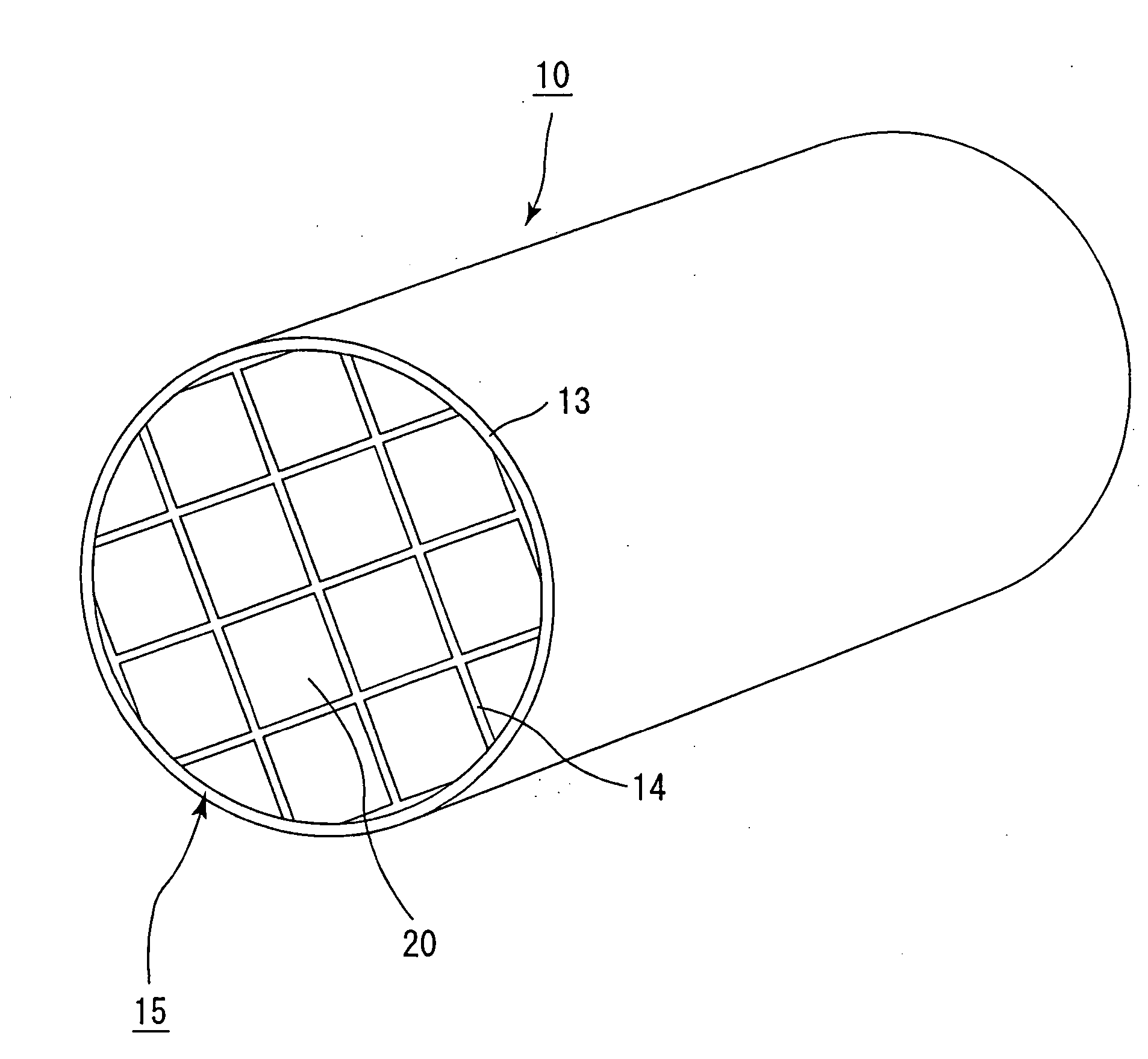
Honeycomb structure

a technology of honeycomb and structure, applied in the field of honeycomb structure, can solve the problems of high pressure loss, containment, and high pressure loss, and achieve the effects of reducing pressure loss fluctuations, increasing the limiting collection amount of particulates, and reducing pressure loss

Active Publication Date: 2005-01-20
IBIDEN CO LTD
View PDF34 Cites 107 Cited by
  • Summary
  • Abstract
  • Description
  • Claims
  • Application Information

AI Technical Summary

Benefits of technology

[0021] The present invention has been made so as to solve the above-mentioned problems, and an object thereof is to provide a honeycomb structural body capable of increasing the limiting collection amount of particulates, reducing the pressure loss in the use and reducing fluctuations in the pressure loss even when the flow rate of exhaust gases from the internal combustion engine fluctuates.

Problems solved by technology

In recent years, particulates, contained in exhaust gases that are discharged from internal combustion engines of vehicles such as buses and trucks and construction equipment, have raised serious problems since those particulates are harmful to the environment and the human body.
However, it has been found that, although these honeycomb structural bodies slightly reduce the rate of increase in pressure loss upon collection of particulates in comparison with a honeycomb structural body in which the aperture ratio on the exhaust gas inlet side and the aperture ratio on the exhaust gas outlet side are equal to each other, they already have high pressure loss even in a state having collected no particulates before the start of use, and consequently have high pressure loss over the entire period of use.
For example, in the case of automobiles, the flow rate of exhaust gases discharged from the internal combustion engine fluctuates every moment in response to the driving modes (such as, flat-way driving, slope-way driving, high speed driving and low speed driving), and when the flow rate of exhaust gases increases, the back pressure caused by the honeycomb structural body becomes higher, resulting in an abrupt rise in pressure loss.
In such cases, since a load is imposed on an engine, the riding comfort of the automobile deteriorates, resulting in a problem of giving the discomfort to the driver.

Method used


Image

  • Honeycomb structure
  • Honeycomb structure
  • Honeycomb structure

Examples


example 1

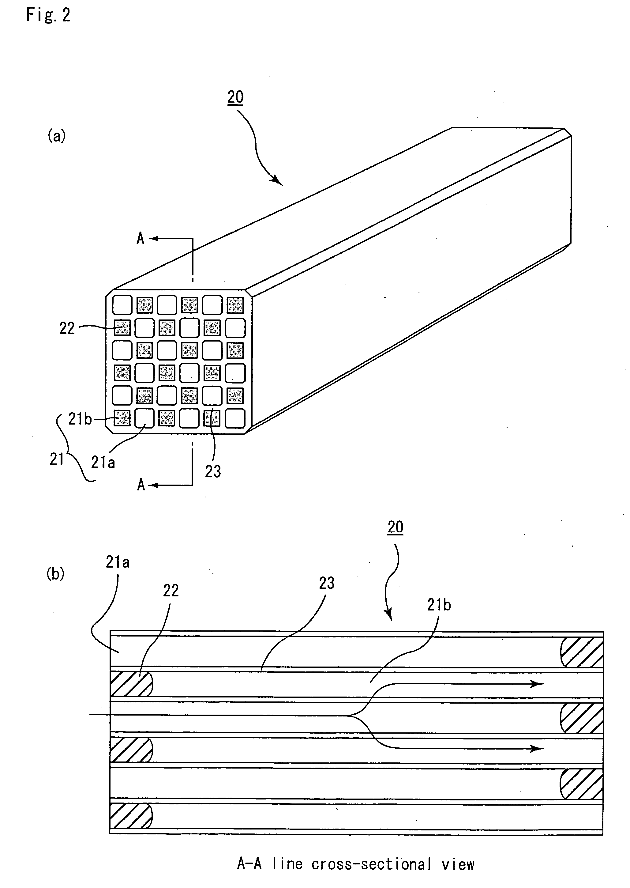
[0152] (1) Powder of α-type silicon carbide having an average particle size of 10 μm (60% by weight) and powder of β-type silicon carbide having an average particle size of 0.5 μm (40% by weight) were wet-mixed, and to 100 parts by weight of the resulting mixture were added and kneaded with 5 parts by weight of an organic binder (methyl cellulose) and 10 parts by weight of water to obtain a mixed composition. Next, after a slight amount of a plasticizer and a lubricant have been added and kneaded therein, the resulting mixture was extrusion-molded so that a formed product, which had almost the same cross-sectional shape as the cross-sectional shape shown in FIG. 3(a), was manufactured.

[0153] Next, the above-mentioned formed product was dried by using a micro-wave drier to form a ceramic dried body, and predetermined through holes were then filled with a paste having the same composition as the formed product. After having been again dried by using a drier, this was degreased at 400...

example 2

[0161] The same processes as Example 1 were carried out except that the cross-sectional shape of the columnar porous ceramic member was made almost the same as a cross-sectional shape shown in FIG. 3(b) so that a honeycomb structural body was manufactured.

[0162] The thickness of the partition wall 43 of a columnar porous ceramic member 40 in accordance with Example 2 was 0.4 mm, the width of a cross section perpendicular to the length direction of the large-capacity through hole 41a was 1.84 mm, and the width of the cross section of the small-capacity through hole 41b was 1.14 mm, and with respect to a cross section perpendicular to the length direction of the columnar porous ceramic member 40, the ratio of areas of the large-capacity through holes 41a was 46.0%, and the ratio of areas of the small-capacity through holes 41b was 18.1%.

[0163] In the columnar porous ceramic member 40 of Example 2, the distance between centers of gravity in cross sections of adjacently located large-...

example 3

[0164] The same processes as Example 1 were carried out except that the cross-sectional shape of the columnar porous ceramic member was made almost the same as a cross-sectional shape shown in FIG. 3(c) so that a honeycomb structural body was manufactured.

[0165] The thickness of the partition wall 53 of a columnar porous ceramic member 50 in accordance with Example 3 was 0.4 mm, the width of a cross section perpendicular to the length direction of the large-capacity through hole 51a was 2.05 mm, and the width of the cross section of the small-capacity through hole 51b was 0.93 mm, and with respect to a cross section perpendicular to the length direction of the columnar porous ceramic member 50, the ratio of areas of the large-capacity through holes 51a was 53.5%, and the ratio of areas of the small-capacity through holes 51b was 12.0%.

[0166] In the columnar porous ceramic member 50 of Example 3, the distance between centers of gravity in cross sections of adjacently located large-...


PUM

PropertyMeasurementUnit
porosityaaaaaaaaaa
porosityaaaaaaaaaa
porosityaaaaaaaaaa

Abstract

A honeycomb structural body which is capable of increasing the limiting collection amount of particulate, reducing the pressure loss in use, and reducing fluctuations in the pressure loss even if the flow rate from an internal combustion engine of exhaust gases fluctuates. The honeycomb structural body is a columnar honeycomb structural body in which a large number of through holes are arranged side by side in the length direction with a partition wall interposed therebetween. The large number of through holes are constituted by a group of large-capacity through holes, with one end thereof sealed to make the total cross-sectional areas perpendicular to the length direction relatively greater, and a group of small-capacity through holes, with the other end thereof sealed to make the total cross-sectional areas relatively smaller. The honeycomb structural body includes a plurality of columnar porous ceramic members.

Description

CROSS REFERENCE TO RELATED APPLICATION [0001] This application claims benefit of priority to Japanese Patent application Nos. 2002-267819 filed on Sep. 13, 2002, and 2003-57631 filed on Mar. 4, 2003, the contents of which are incorporated by reference herein. TECHNICAL FIELD [0002] The present invention relates to a honeycomb structural body used as a filter or the like for removing particulates and the like contained in exhaust gases discharged from an internal combustion engine such as a diesel engine. BACKGROUND ART [0003] In recent years, particulates, contained in exhaust gases that are discharged from internal combustion engines of vehicles such as buses and trucks and construction equipment, have raised serious problems since those particulates are harmful to the environment and the human body. [0004] For this reason, various honeycomb structural bodies, made from porous ceramics, have been proposed as filters capable of collecting particulates from exhaust gases to purify th...

Claims


Application Information

Patent Timeline
Patent Type & Authority Applications(United States)
IPC IPC(8): B01D46/00B01D46/24B01D46/42F01N3/022F01N3/023F01N3/027F01N3/28
CPCB01D46/0063Y10S55/10B01D46/2451B01D46/2459B01D46/247B01D46/2474B01D46/4263B01D2046/2477B01D2046/2481B01D2046/2485B01D2046/2496F01N3/0222F01N3/023F01N3/027F01N3/2828F01N2330/06F01N2330/30F01N2330/34F01N2330/48F01N2450/28Y10S55/30B01D46/2425B01D46/249B01D46/2498B01D46/84B01D46/2484B01D46/2478B01D46/2486
Inventor HONG, SUNGTAEKOMORI, TERUOOHNO, KAZUSHIGE
Owner IBIDEN CO LTD
Why Eureka
Try Eureka