Sheet folding and binding apparatus and method

Inactive Publication Date: 2006-01-10
KANEKO
View PDF21 Cites 5 Cited by
  • Summary
  • Abstract
  • Description
  • Claims
  • Application Information

AI Technical Summary

Benefits of technology

[0010]Preferred embodiments of the present invention provide a novel binding apparatus of a relatively small size, that folds a sheet, and binds stacked folded sheets so that side edges of the bound folded sheets are uniform. The preferred embodiments of the present invention further provide a novel binding apparatus and method that folds a sheet, carrying images of two pages on one side of the sheet and another images of another two pages on the other side of the sheet, at a center portion of the sheet, and that binds folded sheets, which are stacked, at the folded side parts of the folded sheets. The preferred embodiments of the present invention further provide a novel binding apparatus that reliably binds stacked folded sheets without loosening the stack. The preferred embodiments of the present invention further provide a novel binding apparatus that binds folded sheets into a stack of folded sheets so that each of the bound folded sheets is hard to be torn so as not to be easi

Problems solved by technology

Because the stapled sheets are folded at their stapled portions, the side edges of the folded sheets, opposite the stapled and folded side of the folded sheets, are not uniform.
The cutting apparatus is relatively large, heavy and expensive.
The life of a knife used in the cutting apparatus is relatively short.
Further, the consumption of electric power is relatively large.
When the number of printed sheets, which must be folded, is large, the fo

Method used


Image

  • Sheet folding and binding apparatus and method
  • Sheet folding and binding apparatus and method
  • Sheet folding and binding apparatus and method

Examples


Embodiment Construction

[0050]Referring now to the drawings, wherein like reference numerals designate identical or corresponding parts throughout the several views, preferred embodiments of the present invention are described.

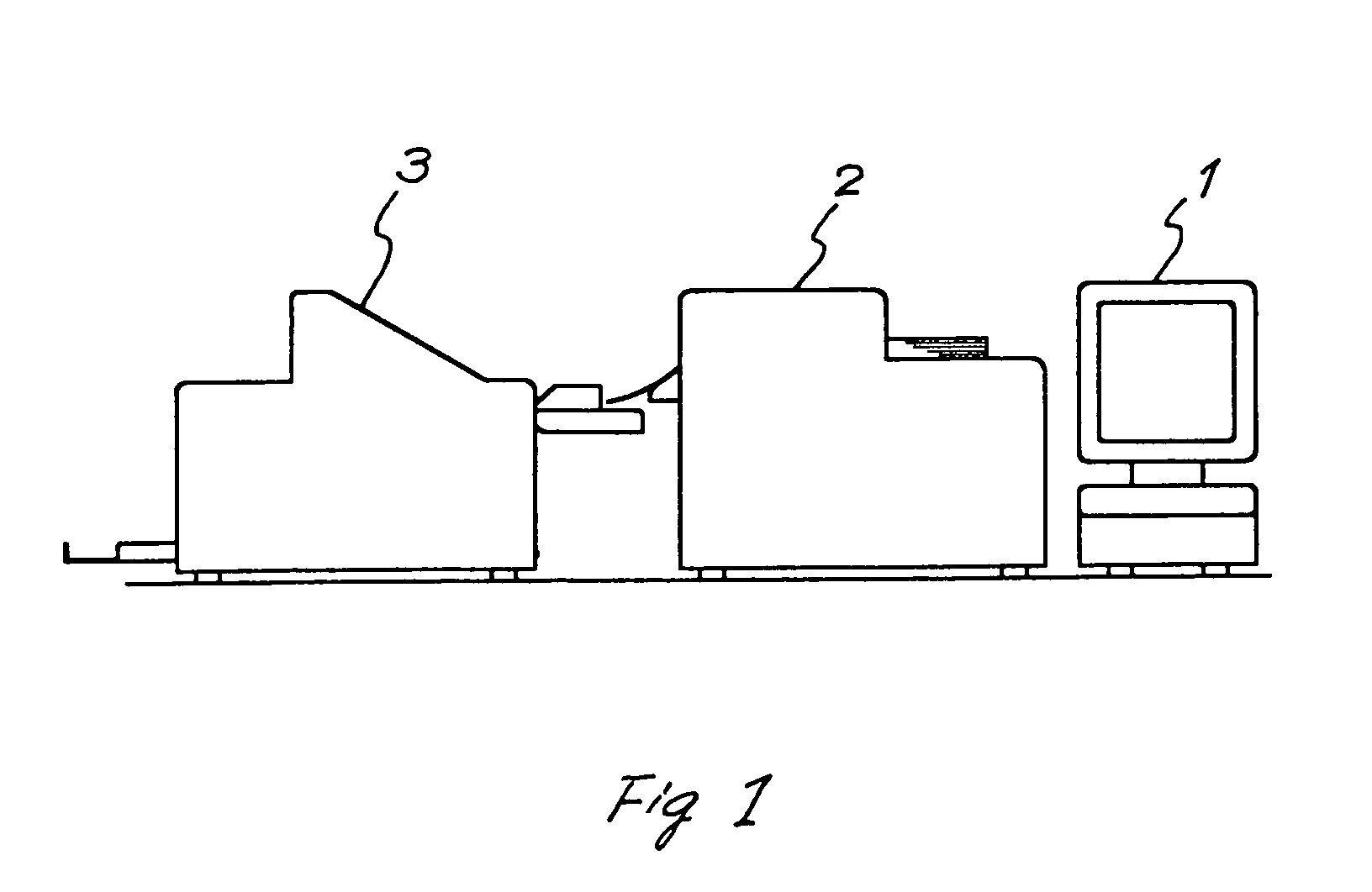
[0051]FIG. 1 is a schematic drawing illustrating an image forming and binding system according to a preferred embodiment of the present invention. Numeral 1 denotes an image formation controller, numeral 2 denotes a printer as an example of an image forming apparatus, and numeral 3 denotes a binding apparatus.

[0052]The image formation controller 1 is for example a personal computer including a display, a keyboard, a scanner, etc. The image formation controller 1 generates image or document data by inputting, or reading an image or a document with the scanner, and editing the data. The image formation controller 1 sets the page for the image or document data, sets various printing and binding instructions for printing the data and binding the printed sheets, e.g., the number of printe...


PUM

PropertyMeasurementUnit
Lengthaaaaaaaaaa
Sizeaaaaaaaaaa

Abstract

A binding apparatus includes a receiving device configured to receive a sheet from outside and convey the sheet, and a sheet folding device configured to fold the sheet, conveyed by the receiving device, in two at a center portion thereof in a direction the sheet is conveyed, so as to be a folded sheet, and convey the folded sheet with the folded portion thereof being a leading edge of the folded sheet. A jogging device includes a jogging table and is configured to receive and jog the folded sheet, conveyed by the sheet folding device, one after another, so as to be stacked into a stack of folded sheets on the jogging table. A binding device is configured to bind the stack of folded sheets stacked on the jogging table at an edge portion of the stack of folded sheets at the side where the folded portion of each folded sheet of the stack of folded sheets is located. A discharging device is configured to discharge the bound stack of folded sheets.

Description

[0001]This is a divisional of application Ser. No. 09 / 896,737, filed Jun. 29, 2001, now U.S. Pat. No. 6,755,410.BACKGROUND OF THE INVENTION[0002]1. Field of the Invention[0003]The present invention relates to a binding apparatus, and in particular relates to a binding apparatus that is connected with a sheet discharging part of an image forming apparatus, such as a printer and a copier, and that folds a sheet received from the image forming apparatus and binds stacked folded sheets at the folded side parts of the folded sheets.[0004]2. Discussion of the Background[0005]A binding technology used in producing weekly magazines is well known. After printed sheets are stacked and jogged, the stacked printed sheets are stapled at their center portions by a stapling device. The stapled sheets are then folded at their stapled portions. Because the stapled sheets are folded at their stapled portions, the side edges of the folded sheets, opposite the stapled and folded side of the folded shee...

Claims


Application Information

Patent Timeline
IPC IPC(8): B65H37/04B42B4/00B42C1/12B42C3/00B65H31/34B65H31/38B65H37/06B65H45/18
CPCB42C1/12B65H31/38B65H2701/1123
Inventor KANEKO, TAMAKI
Owner KANEKO
Why Eureka
Try Eureka