Heliostat for sunlight concentration system and method of controlling the same

a technology of sunlight concentration system and heliostat, which is applied in the direction of optical radiation measurement, comonautical navigation instruments, instruments, etc., can solve the problem of enormous structure of the sunlight concentration system

Inactive Publication Date: 2006-01-10
MITAKA KOHKI
View PDF18 Cites 47 Cited by
  • Summary
  • Abstract
  • Description
  • Claims
  • Application Information

AI Technical Summary

Benefits of technology

[0006]The present invention has focused attention to such a conventional art and provides a heliostat for sunlight concentration systems capable of increasing efficiency in collection of sunlight.
[0007]According to a first technical aspect of the present invention, a heliostat for a sunlight concentration system which constantly reflects and focuses sunlight to a concentration portion has a plurality of concave mirror elements with angles individually changeable, defining a single concave mirror having a predetermined curvature. The angles of the concave mirror elements constituting the concave mirror are respectively changed at least in a direction relating to the diurnal motion of the sun so as to reduce the curvature of the concave mirror when the incident angle of sunlight with respect to the optical axis of the concave mirror is large and to increase the curvature of the concave mirror when the incident angle of sunlight with respect to the optical axis of the concave mirror is small.
[0010]According to a fourth technical aspect of the present invention, a method of controlling a heliostat for a sunlight concentration system which reflects and focuses sunlight to a light concentration portion includes the steps of (i) determining the orientations of main axes of a plurality of concave mirror elements having a first curvature so that the concave mirror elements define a single concave mirror having a second curvature, (ii) controlling the orientation of a main axis of the concave mirror so that incident sunlight is constantly reflected toward the light concentration portion, and (iii) changing the orientations of the main axes of the concave mirror elements so as to reduce the second curvature when the incident angle of sunlight with respect to the main axis of the concave mirror is large, and changing the orientations of the main axes of the concave mirror elements so as to increase the second curvature when the incident angle of sunlight with respect to the main axis of the concave mirror is small.

Problems solved by technology

This conventional art, however, requires the disposition of a number of heliostats over a large area around a concentration portion so as to obtain great thermal energy, leading to an enormous structure of the sunlight concentration system.

Method used


Image

  • Heliostat for sunlight concentration system and method of controlling the same
  • Heliostat for sunlight concentration system and method of controlling the same
  • Heliostat for sunlight concentration system and method of controlling the same

Examples


first embodiment

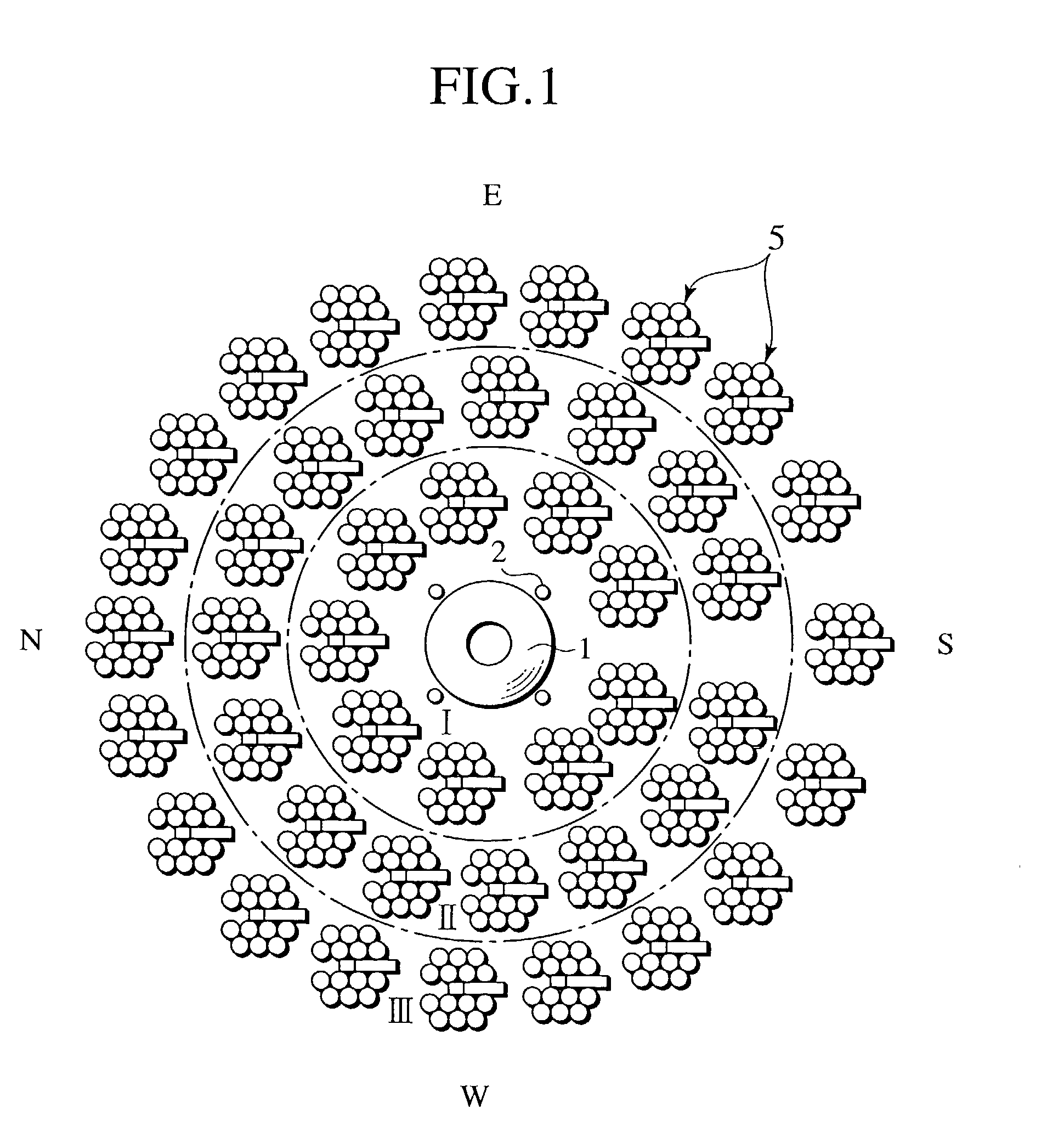
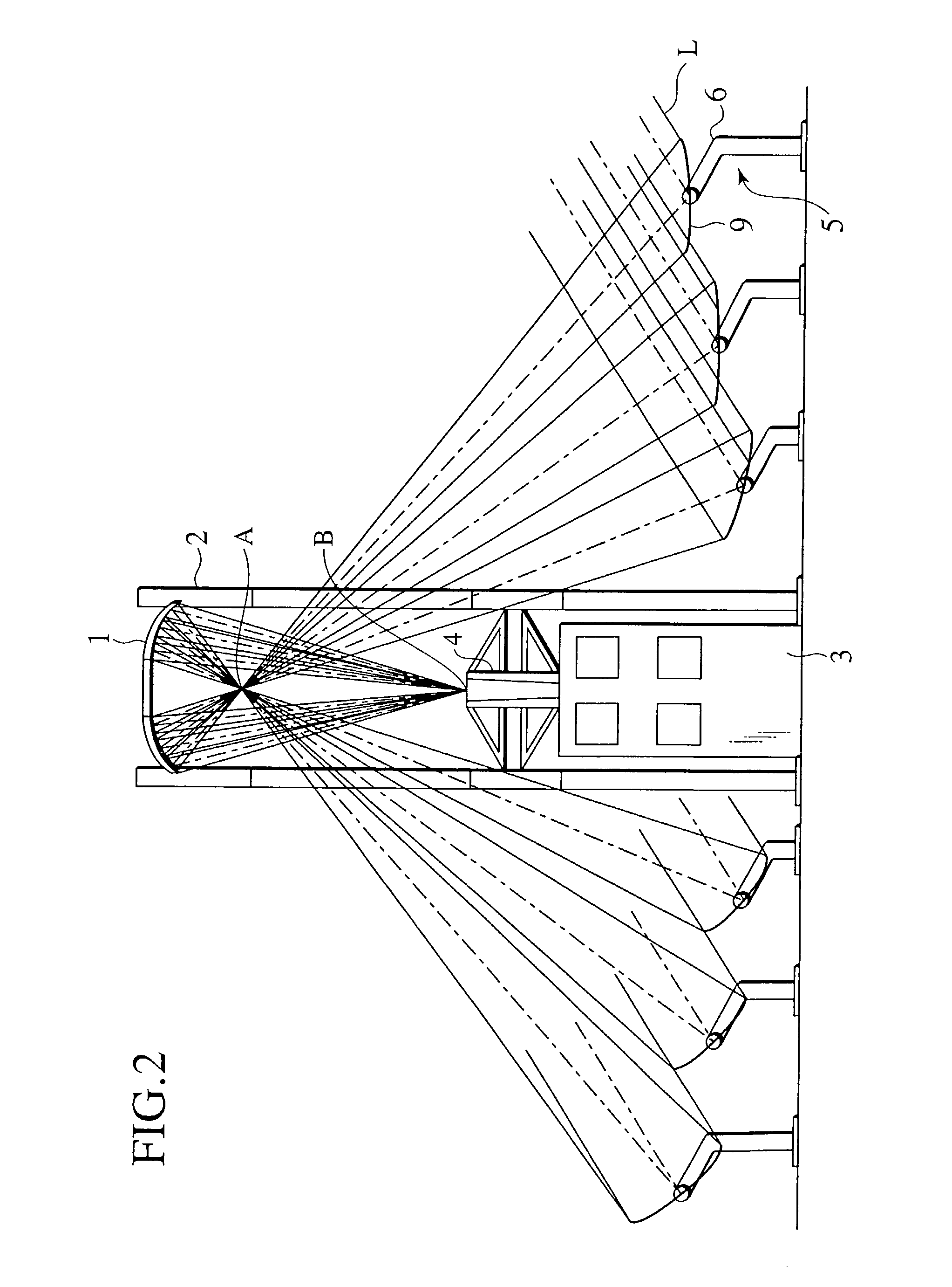
[0021]FIGS. 1–7 illustrate the present invention. Reference numeral 1 denotes an elliptic mirror positioned at a predetermined level with support towers 2, being oriented downward. The mirror surface shape of the elliptic mirror 1 constitutes a portion of an ellipsoid, below which a first focal point A and a second focal point B exist as a concentration portion. A thermal conversion facility 3 for converting sunlight L into thermal energy is established below the elliptic mirror 1. A converging mirror 4 in a tapered tube shape is provided on an upper portion of the thermal conversion facility 3. A number of heliostats 5 are arranged on the ground around the thermal conversion facility 3, encircling the elliptic mirror 1. Sunlight reflected from each heliostat 5, after only passing through the first focal point A, invariably reaches the thermal conversion facility 3 by way of the second focal point B and the converging mirror 4. This allows independent control of the main axis, curva...

third embodiment

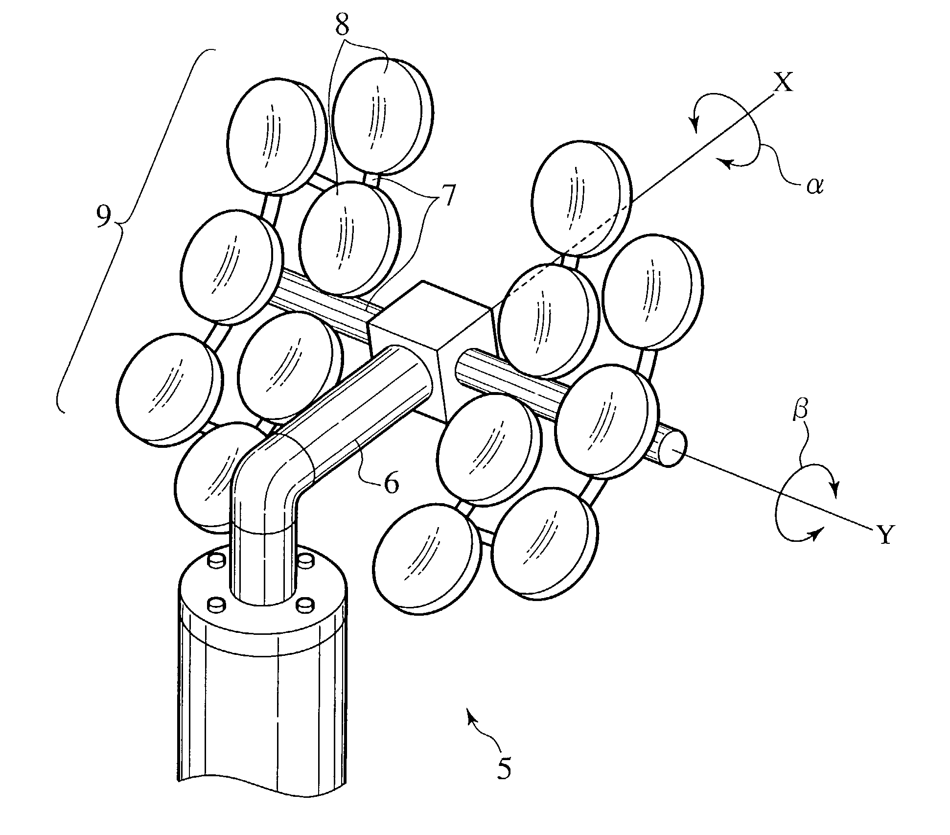
[0035]FIG. 9 illustrates the present invention. A fork 16 rotatable in an azimuth direction H is mounted to an upper portion of a support pole 15 of a heliostat 14. A frame 17 rotatable in an altitude direction V is mounted to the fork 16. A plurality of concave mirror elements 8 are mounted to the frame 17, defining a concave mirror 9. The concave mirror 9 is controlled in orientation using an azimuth sensor and an altitude sensor not shown so as to constantly reflect and focus sunlight L to a fixed concentration portion. The angles of the concave mirror elements 8 are variable in a direction relating to the diurnal motion of the sun detected by the azimuth and altitude sensors not shown. The heliostat 14 of this embodiment is simple in structure because of its alt-azimuth mounting which allows rotation in the azimuth direction H and the altitude direction V. The other components, functions and effects are identical to those of the above embodiments, and the redundant description t...


PUM


Abstract

A heliostat 5 for use in a sunlight concentration system for utilizing sunlight as energy according to this invention has a plurality of small concave mirror elements 8 and reflects and focuses sunlight reflected off the individual concave mirror elements to a light concentration portion as if upon reflection off a single large concave mirror 9. The angles of the concave mirror elements 8 are changed to define a single concave mirror having a predetermined curvature. When the incident angle of sunlight with respect to the concave mirror is large, the curvature is reduced (like a shallow dish). When the incident angle is small, the curvature is increased (like a deep dish).

Description

BACKGROUND OF THE INVENTION[0001]1. Field of the Invention[0002]This invention relates to a heliostat for use in sunlight concentration systems to utilize sunlight as energy source.[0003]2. Description of the Related Art[0004]The effect of carbon dioxide to the global environment is a serious problem. The contemporary society's system relying on petroleum energy is an issue to be solved by every country. In this context, solar energy has received attention as clean energy with no effect on the environment. To utilize sunlight as energy source, it is required to efficiently concentrate sunlight for conversion into thermal energy and convert the thermal energy to electricity. Heliostats are used for the purpose. Each heliostat has a large concave mirror. A number of such heliostats are disposed around a concentration portion. The heliostats' concave mirrors are adjusted in orientation to constantly reflect and focus sunlight to a fixed concentration portion.SUMMARY OF THE INVENTION[00...

Claims


Application Information

Patent Timeline
Patent Type & Authority Patents(United States)
IPC IPC(8): G02B5/10G02B7/182G03B21/00F24S20/20F24S23/70F24S23/71F24S50/20
CPCF24J2/07F24J2/1047F24J2/12F24J2/542F24J2/5427Y10S359/90Y02E10/41Y02E10/42Y02E10/47F24J2002/1076F24S20/20F24S23/71F24S23/80F24S30/452F24S30/458F24S2023/87Y02E10/40
Inventor NAKAMURA, KATSUSHIGE
Owner MITAKA KOHKI
Why Eureka
Try Eureka