Lens grinding processing apparatus

Inactive Publication Date: 2006-01-10
KK TOPCON
View PDF26 Cites 24 Cited by
  • Summary
  • Abstract
  • Description
  • Claims
  • Application Information

AI Technical Summary

Benefits of technology

[0012]Therefore, to solve the above mentioned problems, an object of the present invention is to provide a lens grinding processing apparatus which has a structure to have a drilling part

Problems solved by technology

However, in the conventional arts as above mentioned, they are difficult to retain a main shaft of a tool such as a drill for a drilling in substantially perpendicular to the refractive surface of the rimless lens by only a movement of the tool, and they are likely to occur a grow in size of a device if attempting to provide the main shaft of the tool so as to be in substantially perpendicular to the refractive surface of the rimless lens.
In addition, when the refractive surface of the rimless lens is provided so as to be in substantially perpendicular to the main shaft of the tool by merely inclining a lens rotating shaft itself which holds the rimless lens, the device cannot help being complicated and large scaled in size.
Furthermore, according to the conventional arts, because the hole for fixing the frame cannot be drilled in substantially perpendicular to the refractive surface of the rimless lens, the attachment for fixing cannot be attached in fine appear

Method used


Image

  • Lens grinding processing apparatus
  • Lens grinding processing apparatus
  • Lens grinding processing apparatus

Examples


embodiment 2

[Embodiment 2 of the Present Invention]

[Constitution]

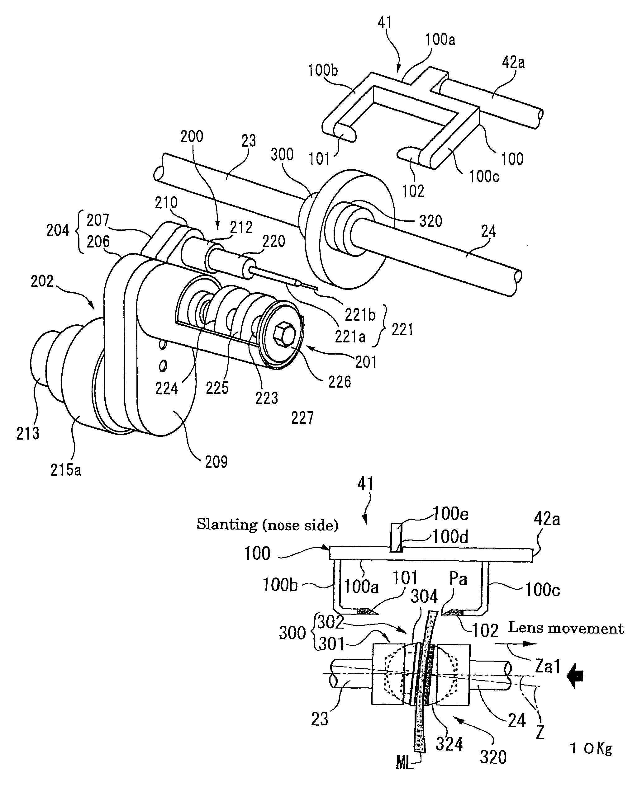
[0250]Although the eyeglass lens ML is slanted and adjusted by driving the measurement shaft 42a in such a manner as to be advanced and retracted in the axis direction with the measurement shaft advancing-retracting means 246 in the embodiment described above, the present invention is not necessarily limited by the above structure. For example, the structure may be set like an embodiment 2 of the present invention shown in FIGS. 30 to 38. Meanwhile, although the basic structure in the embodiment 2 of the present invention is same as the structure in the embodiment 1 and therefore its illustration is omitted, the description of the embodiment 2 of the present invention will be made by using the structure in the embodiment 1 of the present invention. By the way, FIGS. 30 to 38 abbreviatedly show the structure in the FIGS. 13A and 14 by omitting partial of the structure in FIGS. 13A and 14, therefore, the lens absorption device 300 a...


PUM

PropertyMeasurementUnit
Forceaaaaaaaaaa
Angleaaaaaaaaaa
Shapeaaaaaaaaaa

Abstract

A lens grinding processing apparatus of the present invention has lens rotating shafts 23 and 24 for holding an eyeglass lens ML, a lens retaining members (300, 320) fixed respectively to opposed end sections of the lens rotating shafts 23 and 24 capable of slanting adjustably, a drilling device (drilling processing device 200) for drilling a hole for a point frame into the slanted eyeglass lens ML, and a grinding stone (grinding stone 35, chamfering stones 224, 225) for grinding and processing a circumferential part of the eyeglass lens ML.

Description

BACKGROUND OF THE INVENTION[0001]1. Field of the Invention[0002]The present invention relates to a drilling processing apparatus for a rimless lens and a lens grinding processing apparatus to grind and process an edge of a lens for a point frame (hereinafter, abbreviated as rimless lens) and to drill a hole for fixing the point frame.[0003]2. Description of the Prior Art[0004]Conventionally, for example, there has been well known a lens grinding processing apparatus (see Japanese Patent Laid Open Nos. H8-155945 and 2000-218487 or the like) which automatically drills a hole to fix a frame for a point frame and grinds and processes an edge of a lens for the point frame (rimless lens), or a drilling processing apparatus for the rimless lens for drilling a hole for fixing the point frame (see Japanese Patent Laid Open Nos. H8-155806, H9-290399 and H11-10427).[0005]In these cases, since a size of an attachment for fixing the point frame to the rimless lens is not constant, a size of a di...

Claims


Application Information

Patent Timeline
IPC IPC(8): B24B49/00G02C1/02B23B41/00B24B9/14G02C13/00
CPCB24B49/00B24B9/146
Inventor SUZUKI, YASUOOGAWA, YOSHIMASAETO, YASUHITO
Owner KK TOPCON
Why Eureka
Try Eureka