Micromechanical resonator device and method of making a micromechanical device

Active Publication Date: 2006-01-10
THE RGT OF THE UNIV OF MICHIGAN
View PDF8 Cites 141 Cited by
  • Summary
  • Abstract
  • Description
  • Claims
  • Application Information

AI Technical Summary

Benefits of technology

[0051]An object of the present invention is to provide a micromechanical resonator device and a method of making a micromechanical device wherein anchor losses are m

Problems solved by technology

The fabrication process of these off-chip components is not compatible with IC fabrication technology and that is why they are assembled with the ICs on the PCB.
Such as combination between off-chip components and ICs increases manufacturing costs and size of the overall system.
In addition to the size of these off-chip components, they introduce significant insertion losses to the already low power received signal, and they require continuous DC bias for their operation and so consume more power.
Amplifier stages that are usually added after the off-chip components increase the system cost and power requirement.
The power consumption effects the battery life and size.
However, the operational frequency of these comb resonators is limited to several tens of KHz.
However, the developed resonators suffered from:The need for strict vacuum packaging to maintain their high q

Method used


Image

  • Micromechanical resonator device and method of making a micromechanical device
  • Micromechanical resonator device and method of making a micromechanical device
  • Micromechanical resonator device and method of making a micromechanical device

Examples


Example

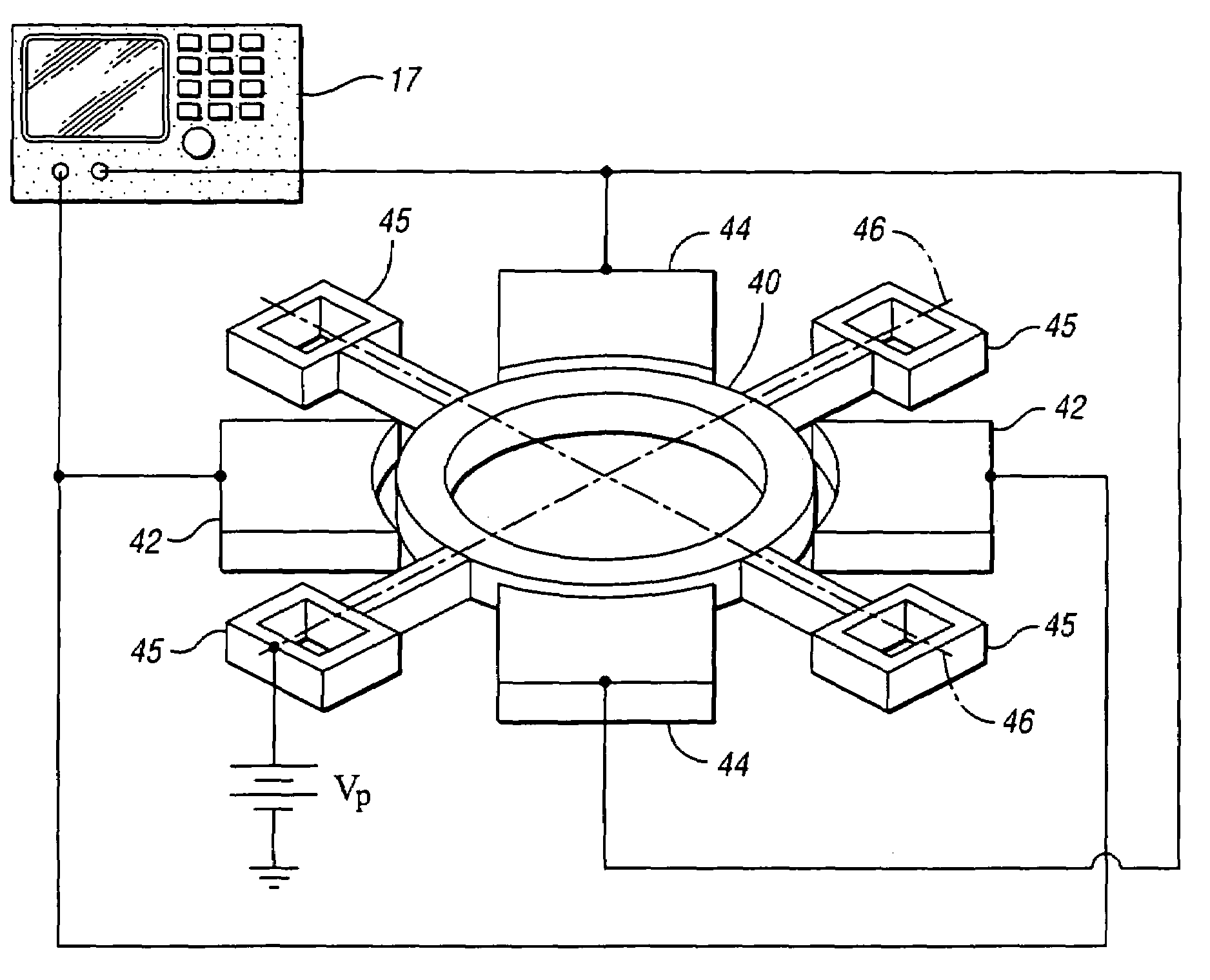
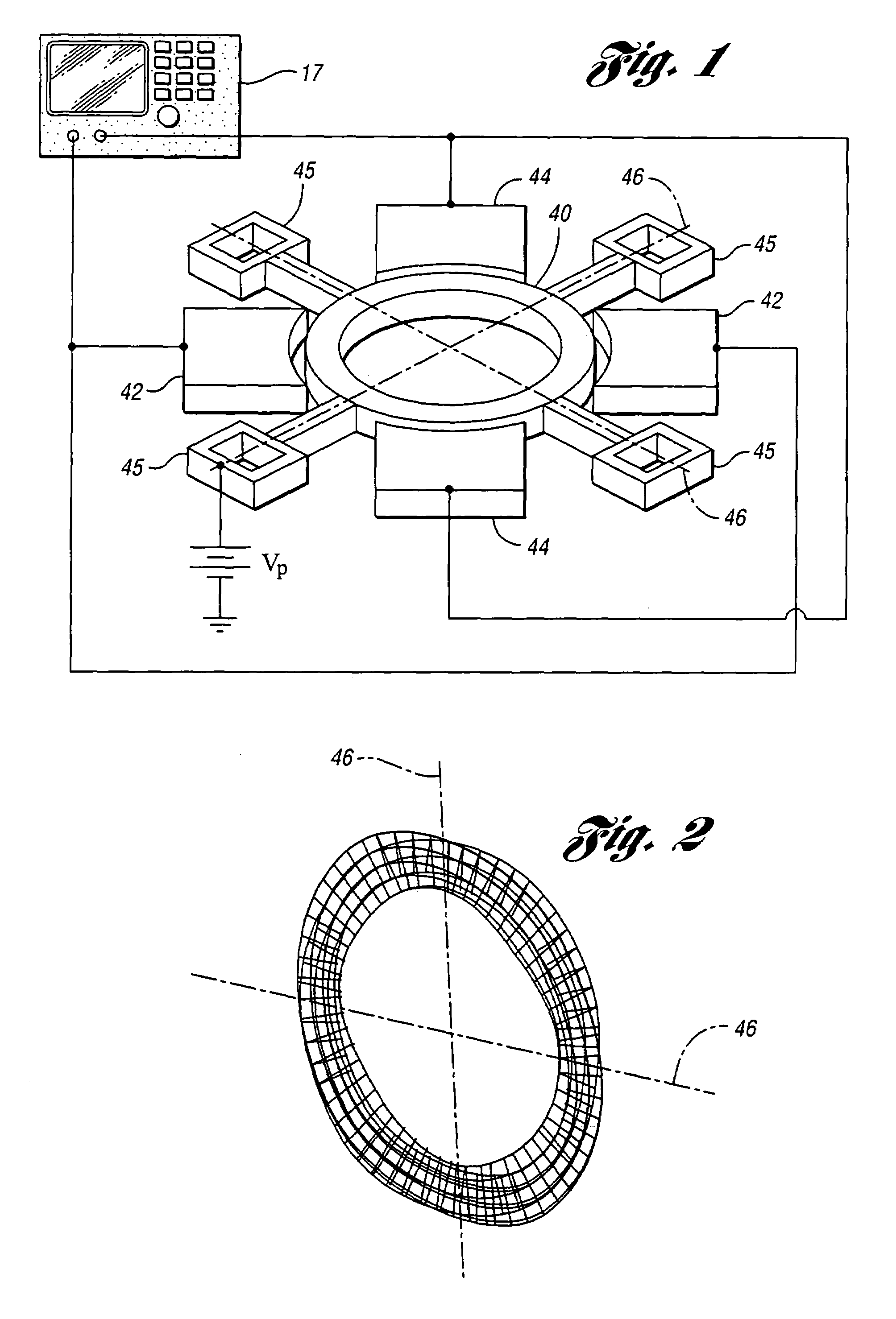
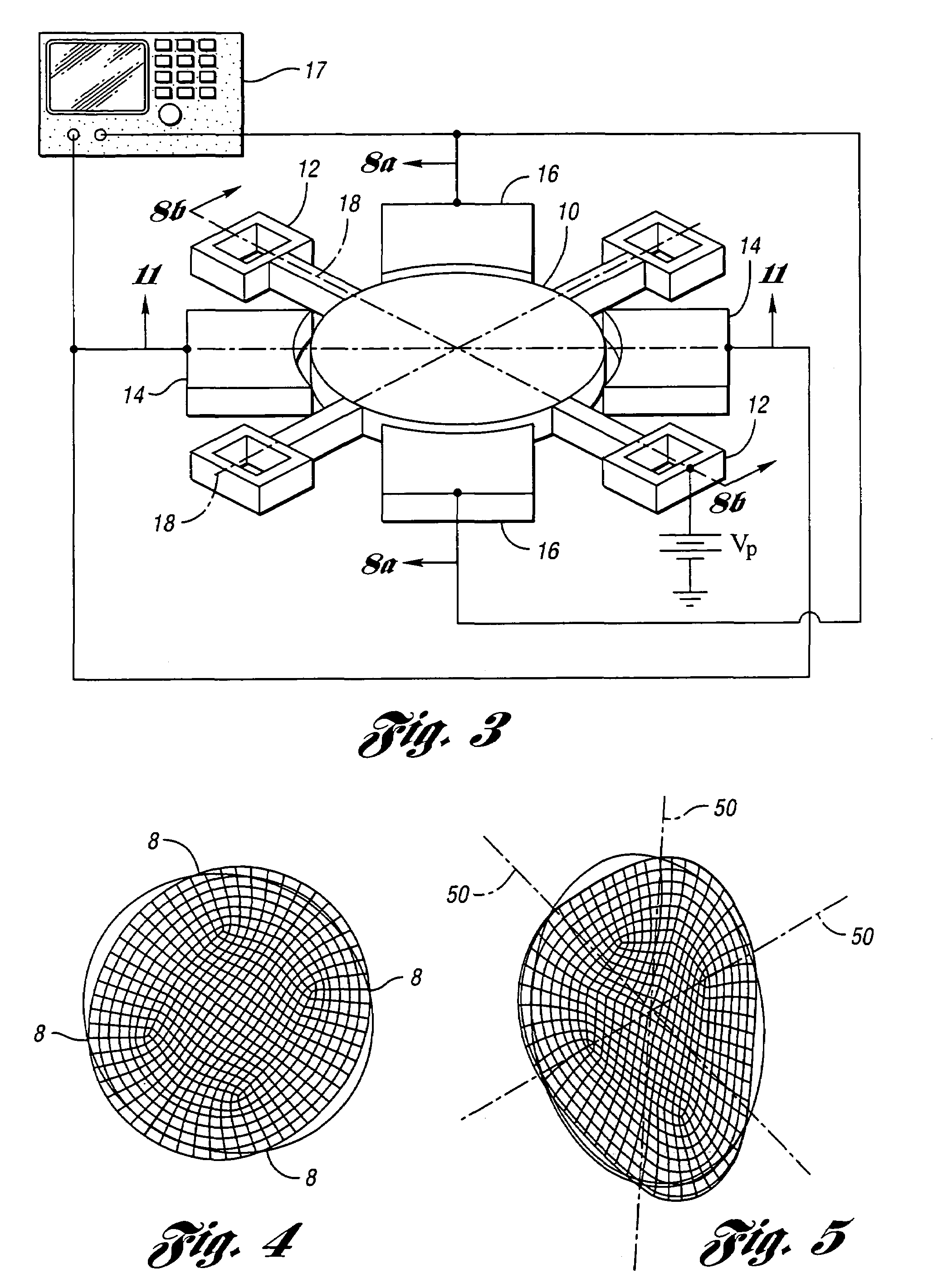
[0083]In one embodiment of a micromechanical resonator device of the present invention, a disk is anchored at the side nodal points using a finite size anchor with absolute zero radial displacement at the side anchors. In contrast to finite size side anchors, a central anchor will not be a real nodal point as it will involve significant radial and tangential displacements. A perspective view of one embodiment of the invention in the form of a wine-glass mode disk resonator 10 with the associated anchoring structure and split electrode configuration is shown in FIG. 3. While four anchors 12 are shown in FIG. 3, it is to be understood that one, two or three anchors could be used without departing from the teachings of the present invention.

[0084]The proposed device is anchored using a novel non-intrusive structure strategically located at real nodal points with almost zero radial displacement. The effect of the tangential displacement is minimized by adjusting the size of the anchor a...


PUM


Abstract

A micromechanical resonator device and a method of making the micromechanical resonator device, as well as other extensional mode devices are provided wherein anchor losses are minimized by anchoring at one or more side nodal points of the resonator device. Lower damping forces are experienced by the resonator device when operated in air.

Description

CROSS-REFERENCE TO RELATED APPLICATION[0001]This application claims the benefit of U.S. provisional application Ser. No. 60 / 434,185, filed Dec. 17, 2002 and entitled “Non-Intrusively Supported Wine Glass Disk Resonator.”STATEMENT REGARDING FEDERALLY SPONSORED RESEARCH OR DEVELOPMENT[0002]This invention was made with Government support under DARPA Grant No. F30602-97-2-0101 and Contract 040455 from NSF ERC. The Government has certain rights in the invention.BACKGROUND OF THE INVENTION[0003]1. Field of the Invention[0004]This invention relates to micromechanical resonator devices and methods of making a micromechanical device.[0005]2. Background Art[0006]The following references are referenced herein:[0007][1] C. T.-C. Nguyen, “Microelectromechanical Components for Miniaturized Low-Power Communications,” / it Proceedings, IEEE MTT-S INTERNATIONAL MICROWAVE SYMPOSIUM RF MEMS WORKSHOP, Anaheim, Calif., Jun. 18, 1999, pp. 48–53.[0008][2] C. T.-C. Nguyen, “Micromechanical Circuits for Commu...

Claims


Application Information

Patent Timeline
IPC IPC(8): H03H9/02H03H9/46H03H9/48H03H3/007H03H9/24
CPCH03H3/0072H03H9/02338H03H9/2436H03H9/2431H03H2009/02503H03H2009/02354H03H3/00H03H9/02
Inventor NGUYEN, CLARK T.-C.ABDELMONEUM, MOHAMED A.
Owner THE RGT OF THE UNIV OF MICHIGAN
Why Eureka
Try Eureka