Motion-adaptive interpolation apparatus and method thereof

a motion-adaptive interpolation and apparatus technology, applied in the direction of picture reproducers using projection devices, signal generators with optical-mechanical scanning, television systems, etc., can solve the problems of screen jitter or a line crawl phenomenon, screen movement up and down slowly, user trembling, etc., to improve picture quality, improve picture quality, and simple hardware structure

Inactive Publication Date: 2006-01-10
LG ELECTRONICS INC
View PDF22 Cites 54 Cited by
  • Summary
  • Abstract
  • Description
  • Claims
  • Application Information

AI Technical Summary

Benefits of technology

[0021]One object of the present invention is to provide a motion-adaptive interpolation method that is capable of improving a picture quality after interpolation by performing a suitable compensation according to motion information.
[0022]Another object of the present invention is to provide a motion-adaptive interpolation apparatus that is capable of improving a picture quality with a simple hardware structure compared to an existing device.
[0023]To achieve these and other advantages and in accordance with the purpose of the present invention, as embodied and broadly described herein, there is provided a motion-adaptive interpolation apparatus and method in which horizontal directional motion information of a field to be currently interpolated is accurately estimated from information of past fields and future fields on the basis of the field to be currently interpolated, and a suitable interpolation is performed according to the estimated motion information.

Problems solved by technology

However, the interlaced scan method has a disadvantage that it causes a screen jitter or a line crawl phenomenon that the screen moves up and down slowly.
Especially, in a still picture without a motion, the trembling of screen is very unpleasant to a user.
Referring to the fourth interpolation method, a picture quality is improved after interpolation, but its hardware construction is considerably complicated.
However, even if the fifth interpolation method is adopted, in case that only the motion between frames is detected, a motion of an object moving instantly or an object moving at a certain speed is hardly detected.
In addition, even in case that a motion between simple fields is detected; it causes an excessive motion detection.
Because of such an excessive motion, a resolution of an image after interpolation is degraded and overall picture quality is also degraded.
It is inevitable that a complicated structure of the overall hardware is required and a manufacturing expense of a circuit for the construction is increased.

Method used


Image

  • Motion-adaptive interpolation apparatus and method thereof
  • Motion-adaptive interpolation apparatus and method thereof
  • Motion-adaptive interpolation apparatus and method thereof

Examples


Embodiment Construction

[0033]The following detailed description of the embodiments of the present invention, as represented in FIGS. 1–4, is not intended to limit the scope of the invention, as claimed, but is merely representative of the presently preferred embodiments of the invention. In the description, same drawing reference numerals are used for the same elements even in different drawings. The matters defined in the description are nothing but the ones provided to assist in a comprehensive understanding of the invention. Thus, it is apparent that the present invention can be carried out without those defined matters. Also, well-known functions or constructions are not described in detail since they would obscure the invention in unnecessary detail.

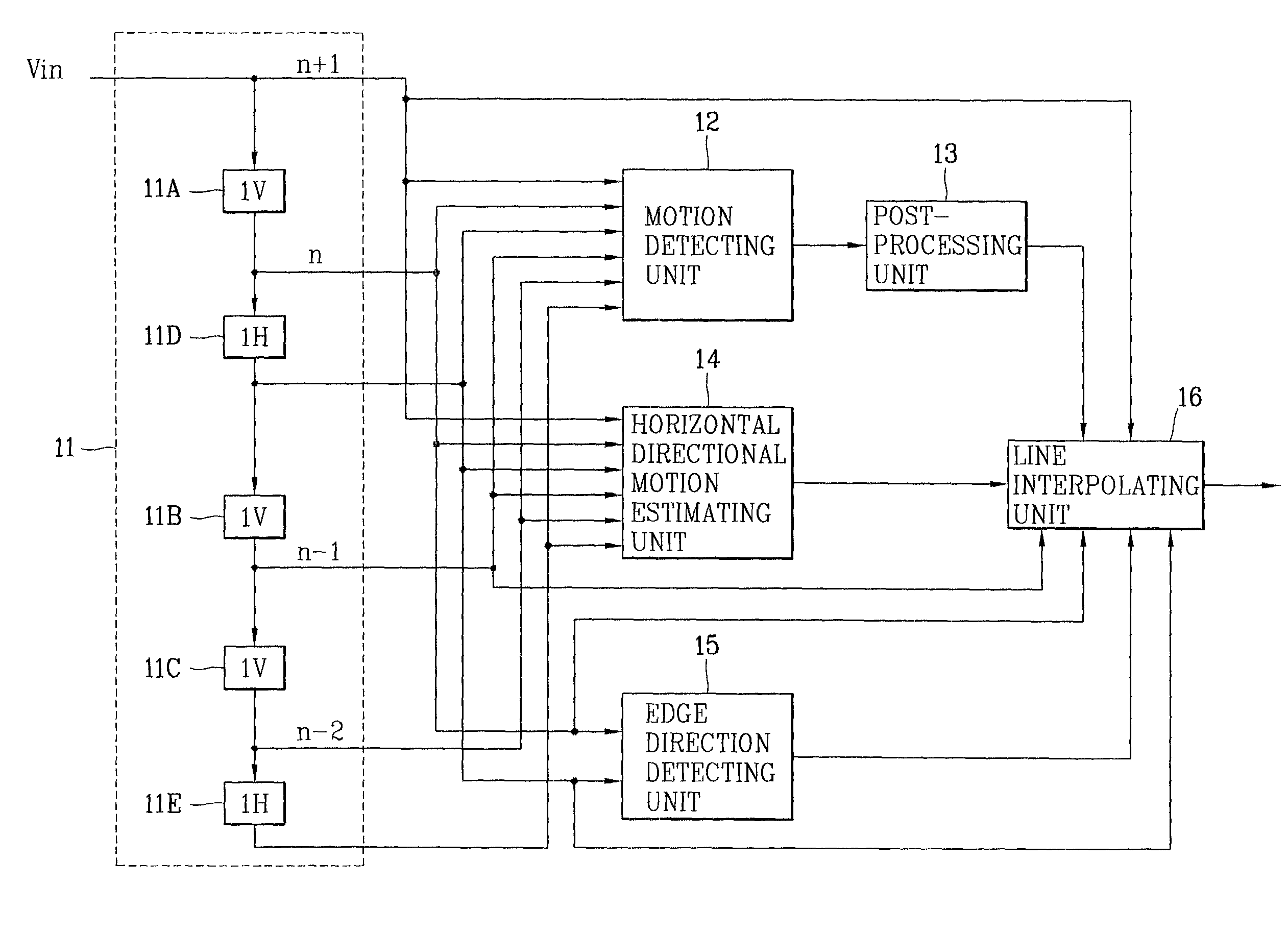
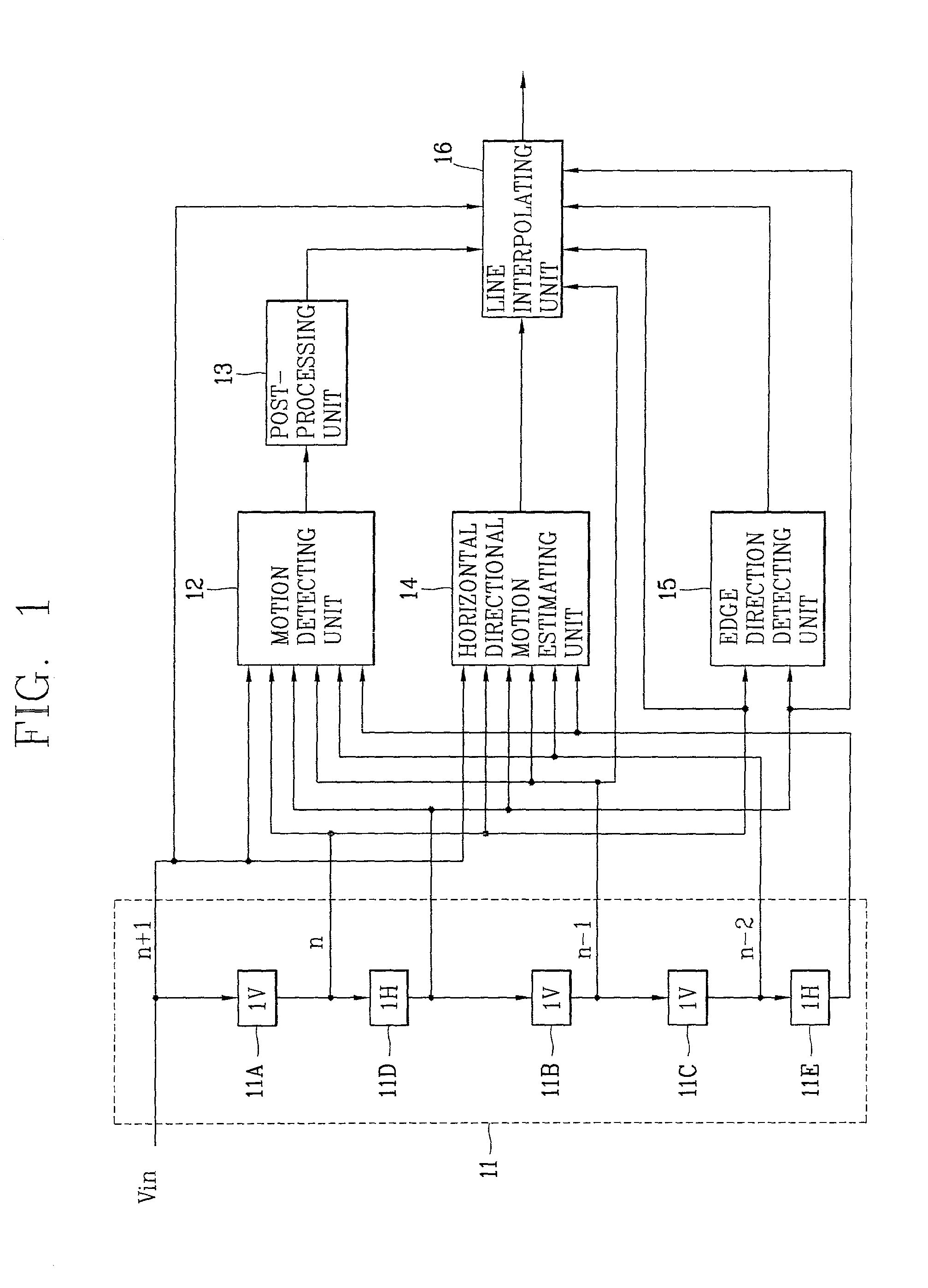
[0034]FIG. 1 is a block diagram of a motion-adaptive interpolation apparatus in accordance with a preferred embodiment of the present invention.

[0035]As shown in FIG. 1, a motion-adaptive interpolation apparatus of the present invention includes: a field ...


PUM


Abstract

A motion-adaptive interpolation apparatus and method are disclosed. After an image signal is received and horizontal directional inter-frame motion information of a field to be currently interpolated is estimation, and interpolating is suitably performed based on the motion information. According to one aspect of the present invention, a basic unit image region is set for a pizel to be interpolated, a block matching error (BME) is obtained by moving the basic unit image region at certain intervals in a different direction, a linear interpolated pixel value is detected in consideration of the block matching error, and a final interpolation value is calculated and outputted by applying a rule and filtering based on the linear interpolated pizel value. Thus, a picture quality is improved after de-interlacing, and a circuit for implementation of the operation is simplified, so that a unit cost can be reduced.

Description

BACKGROUND OF THE INVENTION[0001]1. Field of the Invention[0002]The present invention relates to a de-interlacing of an image sequence, and more particularly, to a motion-adaptive interpolation apparatus and method for accurately performing a de-interlacing.[0003]2. Description of the Related Art[0004]In general, an interlaced scan method has an advantage that a resolution in a vertical direction can be doubled even without raising a refresh rate of a screen, so that the resolution can be effectively improved with a limited frequency band.[0005]However, the interlaced scan method has a disadvantage that it causes a screen jitter or a line crawl phenomenon that the screen moves up and down slowly.[0006]Especially, in a still picture without a motion, the trembling of screen is very unpleasant to a user. A progressive scan method has been introduced to solves this problem.[0007]For example, the NTSC interlaced scan method is performed by scanning an electron beam 60 times a second ove...

Claims


Application Information

Patent Timeline
Patent Type & Authority Patents(United States)
IPC IPC(8): H04N7/01H04N7/32H04N5/44
CPCH04N7/0137H04N7/012H04N7/01
Inventor HAN, DONG ILSHIN, CHANG YONG
Owner LG ELECTRONICS INC
Why Eureka
Try Eureka