Unlock instant, AI-driven research and patent intelligence for your innovation.

Threshold matrix, and method and apparatus of reproducing gray levels using threshold matrix

a threshold matrix and gray level technology, applied in the field of threshold matrix and gray level reproducing methods and apparatuses using the threshold matrix, can solve the problems of low processing speed, poor color reproducibility, and difficulty in predicting the degree of mixture of colors, so as to improve texture and improve the uniformity of dot patterns.

Inactive Publication Date: 2006-01-10
CANON KK
View PDF9 Cites 4 Cited by
  • Summary
  • Abstract
  • Description
  • Claims
  • Application Information

AI Technical Summary

Benefits of technology

[0020]An object of the present invention is to provide a threshold matrix for solving the above drawback in the related background art, increasing uniformity of a dot pattern, and thus improving a problem of texture, a gray level reproduction method which uses this threshold matrix, and a gray level reproduction apparatus which uses this threshold matrix.
[0021]Another object of the present invention is to provide a threshold matrix for improving a potential calculation method and thus remarkably improving conformity at a boundary of threshold matrices, a gray level reproduction method which uses this threshold matrix, and a gray level reproduction apparatus which uses this threshold matrix.
[0022]Still another object of the present invention is to provide a threshold matrix for making the sum of potentials the same in blocks where dot patterns are made the same and thus increasing uniformity of the dot pattern, a gray level reproduction method which uses this threshold matrix, and a gray level reproduction apparatus which uses this threshold matrix.

Problems solved by technology

The image which was output by this method has excellent image quality and resolution, however, processing speed is low because the process itself is complicated.
Further, in a dot pattern which is created by the error diffusion method, generally, a position to be dotted is different according to an input image, whereby it is difficult to predict a degree of mixture of colors.
Thus, there is a drawback that color reproducibility is poor as compared with a later-described systematic dithering method.
However, in this dot pattern, image quality is low because a graininess is insistent or outstand, whereby the random dithering method is hardly being used now.
Since the dot pattern created in this method has a low spatial frequency, its image quality is low in a case where an output device of which the definition is relatively low is used.
However, when an output device of which the definition is relatively low is used, there is a problem that a rough texture (dither pattern) is perceived at a period of the size (16×16 in case of 256 gray levels) of a threshold matrix.
Further, when a periodic pattern is included in the input image, there is a problem that moire may occur in the output image.
For this reason, in the output device of which the definition is relatively low, i.e., several hundreds of dots per inch (dpi), image quality is deteriorated as compared with the error diffusion method, whereby the Bayer-type systematic dithering method is not used for the purpose to obtain a high-quality halftone image.
However, in the dot pattern which is created by using the blue noise masking method, uniformity of the dot distribution is deteriorated according to the number of gray levels, whereby unevenness appears in the output image.
Namely, in the blue noise masking method, the dot pattern of intermediate gray level is optimized and created, and then the dot patterns of high and low gray levels are sequentially created, whereby degree of freedom for dot selection is low nearby the minimum and maximum gray levels, and thus it is difficult to obtain the ideal dot pattern.
Further, a dot pattern creation method which repetitively uses two-dimensional discrete Fourier transform and two-dimensional inverse discrete Fourier transform is complicated, whereby there is a problem that it takes time to create the dot pattern.

Method used


Image

  • Threshold matrix, and method and apparatus of reproducing gray levels using threshold matrix
  • Threshold matrix, and method and apparatus of reproducing gray levels using threshold matrix
  • Threshold matrix, and method and apparatus of reproducing gray levels using threshold matrix

Examples


first embodiment

(First Embodiment)

[0136]The procedure of creating one of the masks having the feature according to the present embodiment will be explained with reference to the flow chart shown in FIG. 1.

[0137]First, in the step S1, the basic structure of the mask is determined. The mask in the present embodiment is the 256×256 square mask for 256 gray levels. FIG. 8 is a diagram showing the method of arranging the mask when the input image is larger than the mask.

[0138]In FIG. 8, the gray 256×256 pixels correspond to the size of one mask. In a case where the output device is a printer, the direction (I) represents the main scan direction such as an ink emission head direction or the like, and the direction (II) is the sub scan direction such as a sheet feed direction or the like.

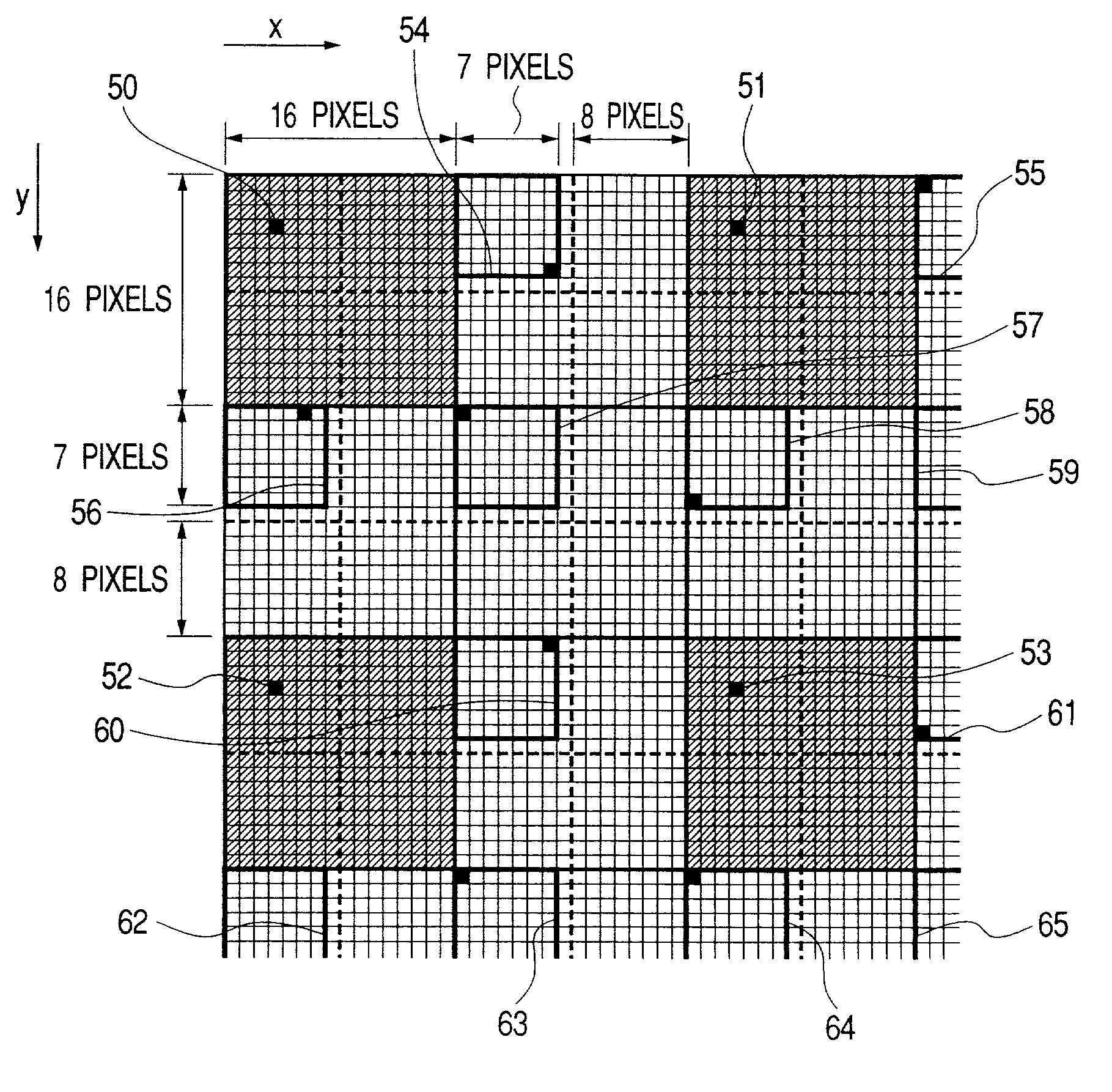
[0139]When the dot pattern of the 256×256 pixels created by using the mask of the present embodiment is divided into the blocks each including the 16×16 pixels as indicated by the solid line in FIG. 3 and further divided ...

second embodiment

(Second Embodiment)

[0159]The method of creating one of the masks having the feature according to the present embodiment will be explained with reference to the flow chart shown in FIG. 1.

[0160]First, in the step S1, the basic structure of the mask is determined. The mask in the present embodiment is the 256×256 square mask for 256 gray levels. When the input image is larger than the mask size, the mask is repeatedly used while being shifted toward the longitudinal direction by the 128 pixels as shown in FIG. 11.

[0161]In FIG. 11, the gray 256×256 pixels correspond to the size of one mask. In a case where the output device is a printer, the direction (I) represents the main scan direction such as an ink emission head direction or the like, and the direction (II) is the sub scan direction such as a sheet feed direction or the like.

[0162]When the dot pattern of the 256×256 pixels created by using the mask of the present embodiment is divided into the blocks each including the 16×16 pixe...

third embodiment

(Third Embodiment)

[0181]The method of creating one of the masks having the feature according to the present embodiment will be explained with reference to the flow chart shown in FIG. 1.

[0182]First, in the step S1, the basic structure of the mask is determined. The mask in the present embodiment is suitable for 256 gray levels. When the input image is larger than the mask size, the mask is repeatedly used according to a method as explained with respect to FIG. 16.

[0183]In FIG. 16, the gray cross corresponds to the size of one mask. In a case where the output device is a printer, the direction (I) represents the main scan direction such as an ink emission head direction or the like, and the direction (II) is the sub scan direction such as a sheet feed direction or the like.

[0184]Such a mask arrangement method is equivalent to the case where the gray rectangular mask of the 64×320 pixels is used while being shifted by the 128 pixels, as shown in FIG. 17. Hereinafter, in consideration ...


PUM


Abstract

When one-to-one correspondence is made between each pixel of an original image and each element of a threshold matrix, a density of each pixel in an output image is represented by binary or multivalue, and a dot pattern of which the size corresponds to the threshold matrix is divided into small blocks, the threshold matrix is created such that the number of dots in each of all the blocks is made equal in all gray levels, the dot patterns in the plural blocks are made mutually the same in all the gray levels, and at a boundary of the blocks where the dot patterns are made mutually the same, the dots are increased while taking conformity of the dot patterns, or the threshold matrix is created such that order of dot increase is controlled between the blocks where the dot patterns are made mutually the same and the other blocks. Thus, the threshold matrix by which uniformity of the dot pattern is increased and a problem of texture is improved, a gray level reproduction method which uses this threshold matrix, and a gray level reproduction apparatus which uses this threshold matrix are provided.

Description

BACKGROUND OF THE INVENTION[0001]1. Field of the Invention[0002]The present invention relates to a threshold matrix and gray level reproducing method and apparatus using the threshold matrix, and more specifically to a threshold matrix and gray level reproducing method and apparatus using the threshold matrix for converting input image data into binary or multivalue data in a gray level reproducing process.[0003]2. Related Background Art[0004]One of most used methods among conventionally known gray level reproducing methods is an error diffusion method.[0005]In the error diffusion method, an input image is converted into a binary image or a multivalue image by comparing each pixel of this input image with a threshold, and at this time, an error (a quantizing error) between input and output values is weighted and diffused to predetermined adjacent pixels to preserve an image density. The image which was output by this method has excellent image quality and resolution, however, proces...

Claims


Application Information

Patent Timeline
Patent Type & Authority Patents(United States)
IPC IPC(8): G06K15/00B41J2/52G06T5/00H04N1/40H04N1/405
CPCH04N1/4051
Inventor OKINAKA, KEIJISUZUKI
Owner CANON KK
Features
  • R&D
  • Intellectual Property
  • Life Sciences
  • Materials
  • Tech Scout
  • Unparalleled Data Quality
  • Higher Quality Content
  • 60% Fewer Hallucinations
Learn More