
Damped control of a micromechanical device

a micromechanical device and control technology, applied in the field of micromechanical devices, can solve the problems of introducing a significant contrast loss, affecting the performance of the device, so as to reduce the undesirable mechanical transient response, reduce overshoot and oscillation, and reduce the transient resonance of the dmd mirror

Active Publication Date: 2006-01-10
TEXAS INSTR INC
View PDF13 Cites 28 Cited by
  • Summary
  • Abstract
  • Description
  • Claims
  • Application Information

AI Technical Summary

Benefits of technology

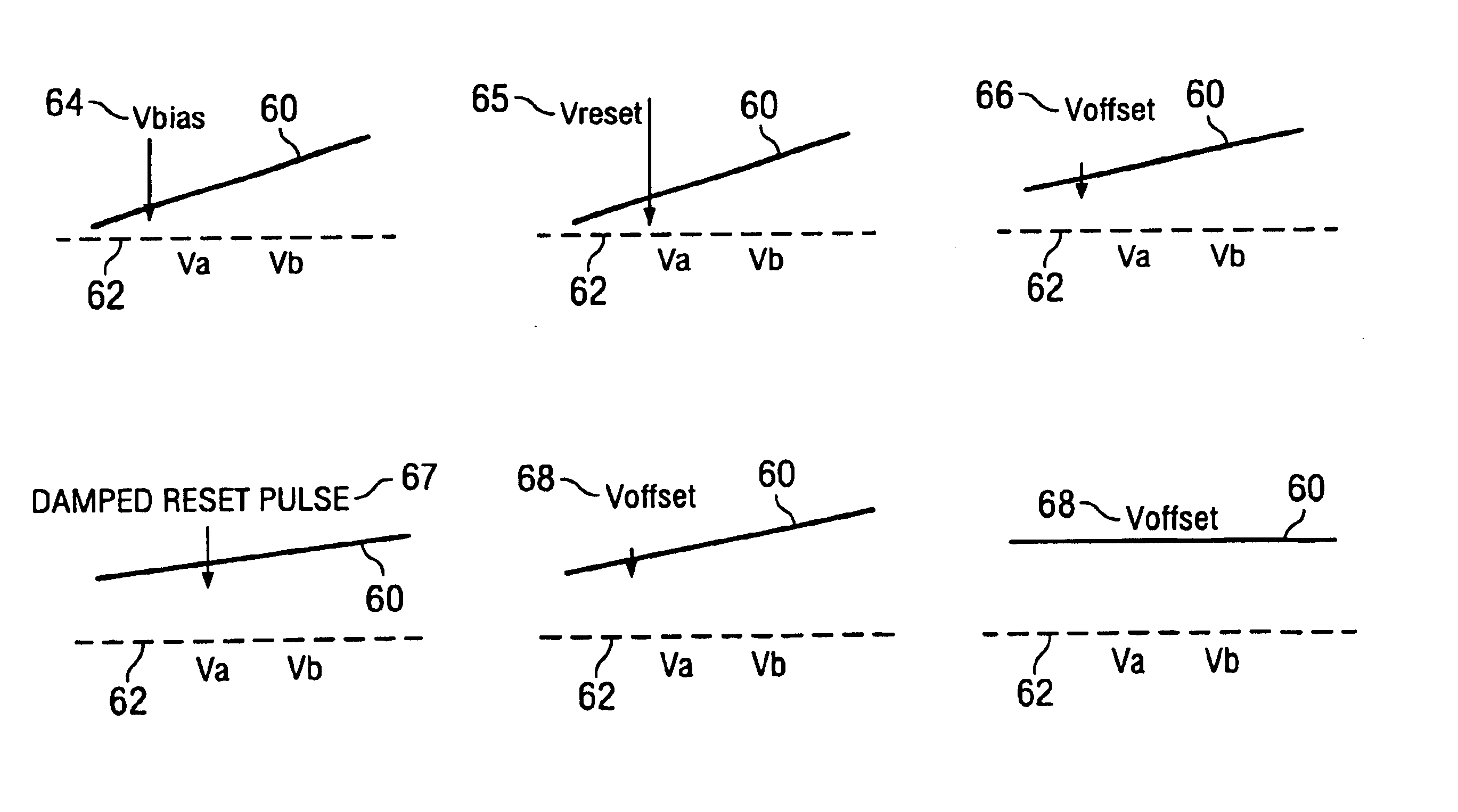
[0012]These and other problems are generally solved or circumvented, and technical advantages are generally achieved, by preferred embodiments of the present invention which utilize a damping function to reduce undesirable mechanical transient responses to control signals. In one aspect of the present invention, the damping function may be used to reduce overshoot and oscillation when a DMD mirror is driven from a landing plate to the flat or neutral position. In another aspect of the present invention, the damping function may be used to reduce transient resonance of a DMD mirror when the mirror is driven to a landing plate.
[0014]In accordance with another preferred embodiment of the present invention, a system for operating a digital micromirror device having at least one micromirror comprises applying a reset voltage pulse to the micromirror, then applying an offset voltage to the micromirror immediately after the reset voltage pulse. A bias voltage is applied to the micromirror immediately after the offset voltage. The bias voltage is applied for a damping delay period. A triangular damping pulse is applied to the micromirror after the damping delay period, and then the bias voltage is reapplied to the micromirror. The triangular damping pulse generally reduces a transient resonant vibration of the micromirror on a landing plate.
[0015]An advantage of a preferred embodiment of the present invention is that it provides more stable and reliable mechanical switching operation, and enables shorter mechanical switching time that allows less minimum expose time and increased color bit depth. This in turn may provide a reduction in video noise and contouring.
[0016]A further advantage of a preferred embodiment of the present invention is that it provides increased yield. In particular, while the LSB may be a damped reset-release bit, the next bit, which may be fast clear, may be significantly longer. Thus, fast clear wait time may be increased, which relaxes the criteria for yield.
[0017]Another advantage of a preferred embodiment of the present invention is that there generally is no need to change the current DMD pixel design, structure, or process (except for modifying control functions to implement the damping function).
[0018]Yet another advantage of a preferred embodiment of the present invention, when used to dampen mirror resonance on landing on a landing plate, is that there may be less mechanical friction between the mirror landing tip and the mirror landing plate, resulting in less mechanical wear on the passivation layer.

Problems solved by technology

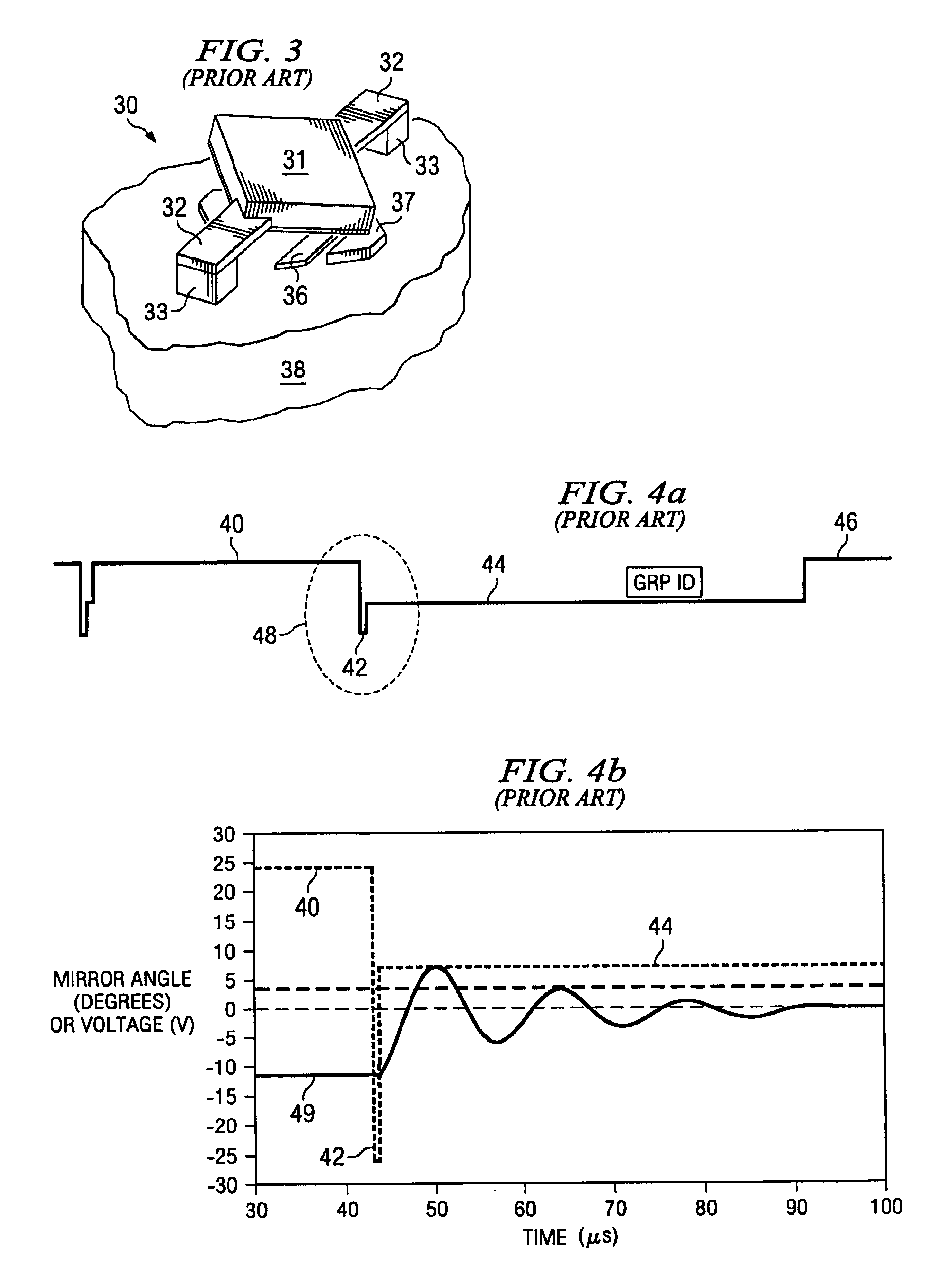
One potential disadvantage with the mechanical nature of a DMD mirror is that a transient response typically is seen just after the mirror tip (spring tip) lands on a landing plate.
Moreover, even at that level, there may be a significant yield loss.
One potential disadvantage with the prior art reset-release pulse sequence is that it may introduce a significant loss in contrast (e.g., about 30%).
In addition, it may introduce a potential residual image artifact with hinge memory over the device lifetime.
These disadvantages generally are due to a significant overshoot of the mirror into the pupil of the optical system after launch.

Method used


Image

  • Damped control of a micromechanical device
  • Damped control of a micromechanical device
  • Damped control of a micromechanical device

Examples


Embodiment Construction

[0037]The making and using of the presently preferred embodiments are discussed in detail below. It should be appreciated, however, that the present invention provides many applicable inventive concepts that can be embodied in a wide variety of specific contexts. The specific embodiments discussed are merely illustrative of specific ways to make and use the invention, and do not limit the scope of the invention.

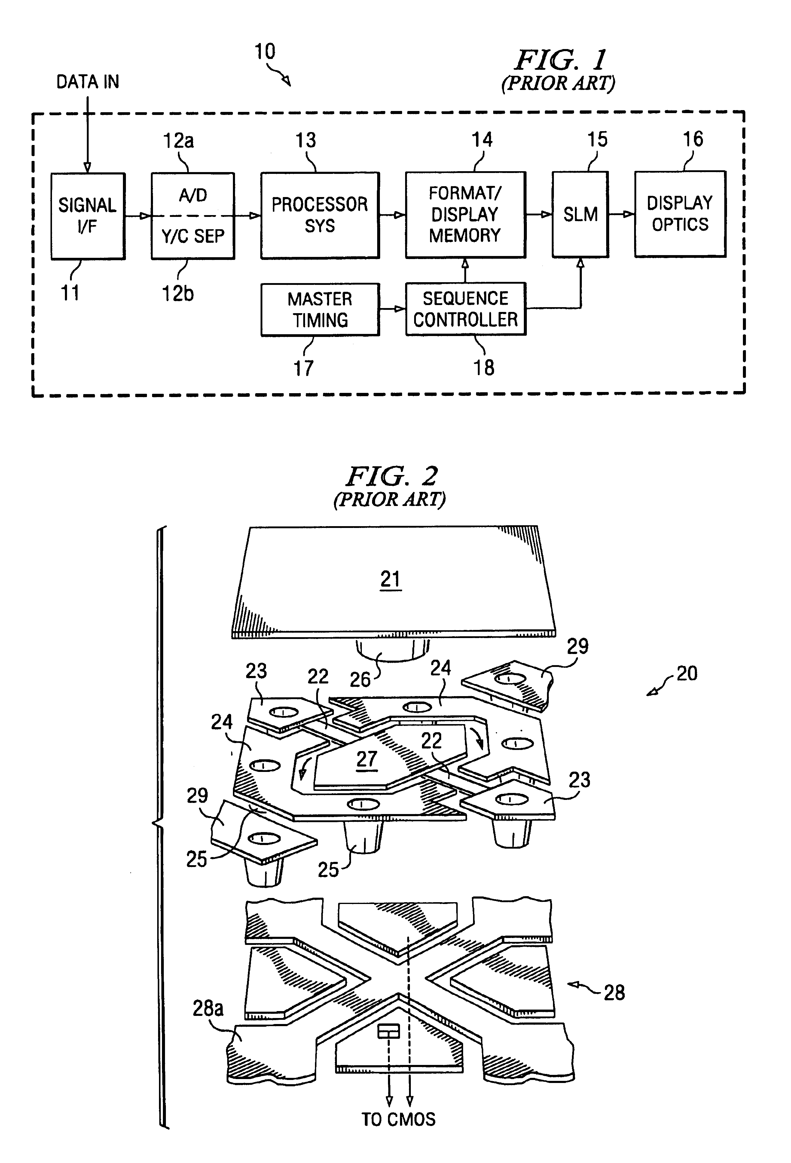
[0038]The present invention will be described with respect to preferred embodiments in a specific context, namely a DMD with a damped reset and release. The invention may also be applied, however, to other types of spatial light modulators, to other micro-electromechanical system (“MEMS”) devices having movable elements that move in response to electrostatic attraction, or to other MEMS devices utilizing transient control of movable elements.

[0039]One application of DMDs is for forming images where the DMD has an array of deflectable mirrors that selectively reflect light to ...


PUM


Abstract

Device and method for a damping function to reduce undesirable mechanical transient responses to control signals. In one aspect of the present invention, the damping function may be used to reduce overshoot and oscillation when a digital micromirror is driven from a landing plate to the flat or neutral position. In another aspect of the present invention, the damping function may be used to reduce transient resonance of a digital micromirror when the micromirror is driven to a landing plate.

Description

[0001]This application claims the priority benefit of U.S. Provisional Application Ser. No. 60 / 472,079, entitled “Damped Reset for a Digital Micromirror Device,” filed on May 20, 2003, which application is hereby incorporated herein by reference.CROSS-REFERENCE TO RELATED APPLICATIONS[0002]This application relates to the following co-filed and commonly assigned patent applications: Ser. No. 10 / 749,469, entitled “Damped Control of a Micromechanical Device;” and Ser. No. 10 / 749,432, entitled “Damped Control of a Micromechanical Device,” which applications are hereby incorporated herein by reference.TECHNICAL FIELD[0003]The present invention relates generally to micro-mechanical devices, and more particularly to a device and method for damping the movable elements of such devices.BACKGROUND[0004]Generally, video display systems based on spatial light modulators (SLMs) are increasingly being used as an alternative to display systems using cathode ray tubes (CRTs). SLM systems generally ...

Claims


Application Information

Patent Timeline
IPC IPC(8): G02B26/00G02B26/08G02B7/182G09G3/34
CPCG02B26/0841
Inventor CHU, HENRY CHUNG-HSINGONZALEZ, ARMANDOOUDAL, THOMAS D.
Owner TEXAS INSTR INC
Learn More