
Control device for controlling the position of a marine seismic streamer

a technology of control device and streamer, which is applied in the direction of underwater equipment, special-purpose vessels, instruments, etc., can solve the problems of prior-art bird designs that cannot correct the transverse alignment of streamers, birds are too cumbersome to allow permanent fixation, and the hydrodynamic stability of prior-art designs is questionabl

Inactive Publication Date: 2006-01-10
ATLAS ELEKTRONIK UK
View PDF11 Cites 37 Cited by
  • Summary
  • Abstract
  • Description
  • Claims
  • Application Information

AI Technical Summary

Benefits of technology

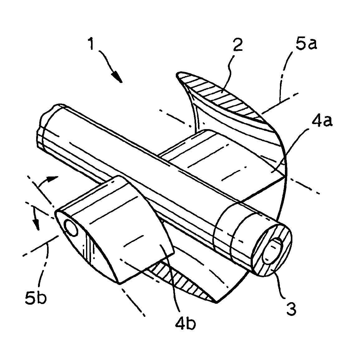
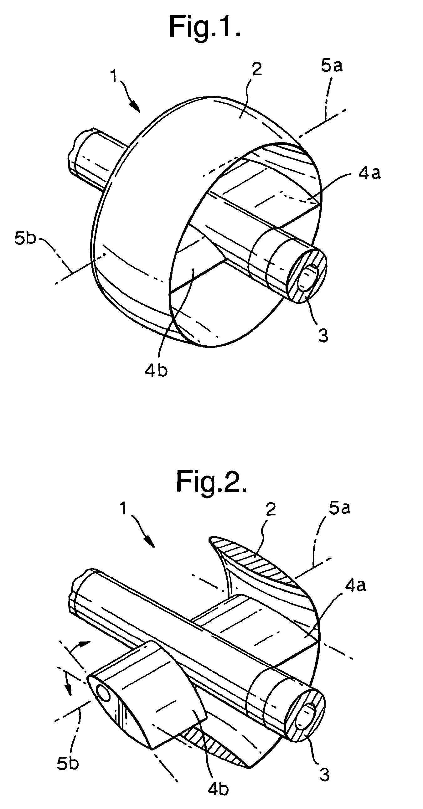
[0016]It is to be understood that for the purposes of this invention, the term annular aerofoil is intended to include annular rings with varied cross sectional, aerodynamic profiles. These cross sectional shapes may range from a simple oval or elliptical shape to more complex aerofoil designs. The annular aerofoil is mounted about the streamer with its attachment points as near as possible coplanar with its centre of lift, thus minimising the forces required to control its orientation.
[0018]The control device of the invention may be removably attachable to a streamer or, preferably, may be permanently fixed to a streamer. The design of the control devices of the invention are sufficiently robust and compact that they may be permanently fixed to a streamer and may be wound with the streamer onto a winch of appropriate design for convenient storage and deployment.

Problems solved by technology

However, in general, the birds of prior art designs are not able to correct the transverse alignment of the streamers, if, for example, a cross current affects a streamer's position.
Another problem of many prior art designs is that the birds are too cumbersome to allow them to be permanently fixed to the streamers, the birds, necessarily having to be attached or removed from the streamers at intervals as the streamers are deployed or retrieved.
Furthermore, the hydrodynamic stability of prior art designs is questionable, particularly after a period of man-handling in the field.

Method used


Image

  • Control device for controlling the position of a marine seismic streamer
  • Control device for controlling the position of a marine seismic streamer
  • Control device for controlling the position of a marine seismic streamer

Examples


example 2

Forces Generated to Control Annular Aerofoil Angle of Incidence

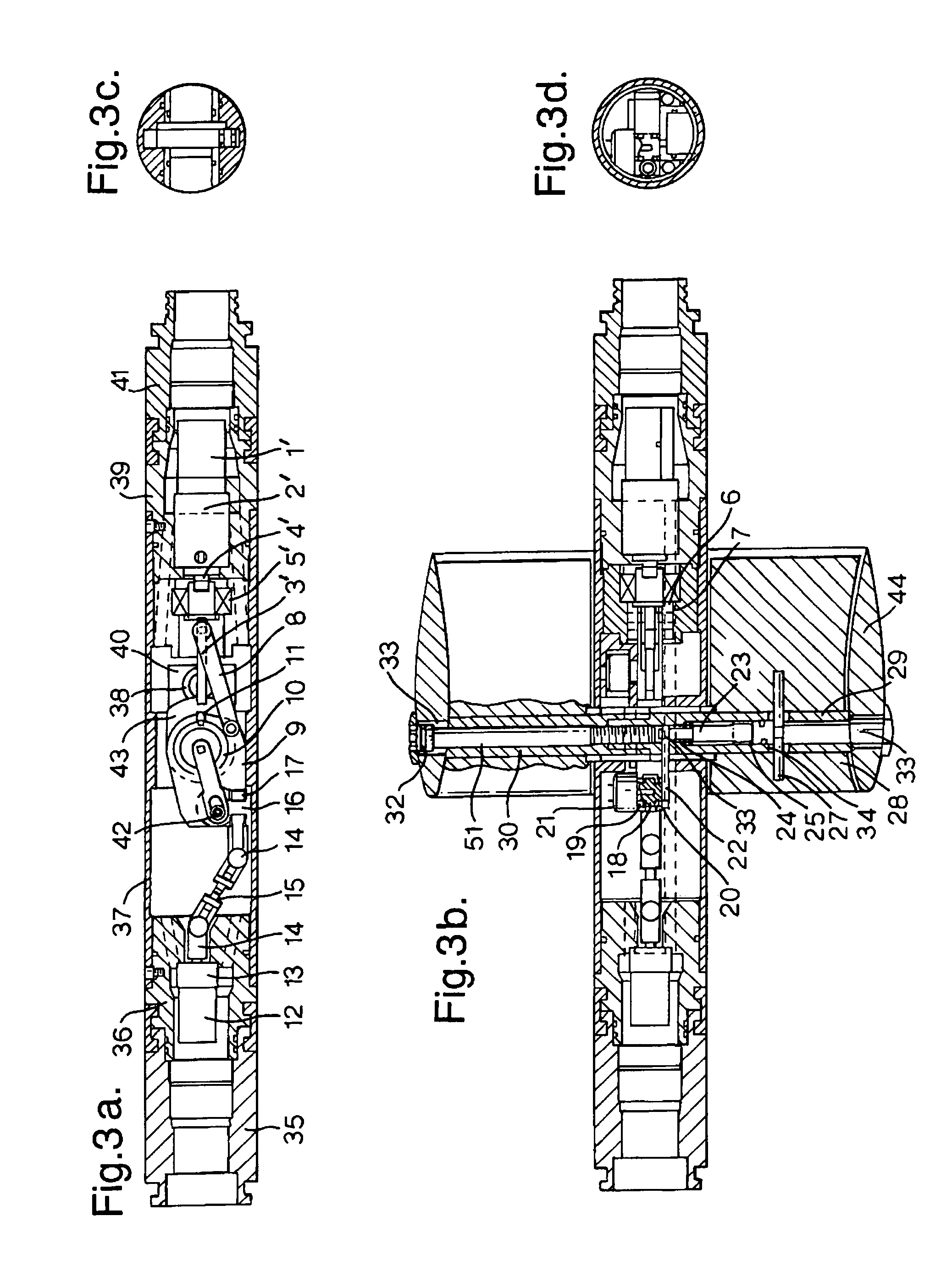
[0063]The motor selected to control the ring wing angle of attack is a Portescap 28 L 28, this has a maximum intermittent torque rating of 57 mNm. The proposed gear box is from the same manufacturer, and is an R 32.0 with a reduction of 72.3: 1, and an efficiency of 65%. It has a continuous torque rating of 4.5 Nm, and a static torque rating of 20 Nm. If the intermittent rating of the motor is multiplied by the gear reduction and the efficiency:

0.57×72.3×0.65=2.679 Nm

[0064]This is well within the gear box's continuous rated capacity.

[0065]The gear box drives an M6×1.0 screw thread. It is known that to tighten the average M6 screw to yield requires 2.8 kgm of torque, and this will produce a load of 2030 kg.

[0066]Because the screw is mounted in a roller bearing, it is reasonable to assume that the torque required to overcome the friction in the head end of the screw will sensibly be eliminated. It would also be a conservat...

example 3

Annular Aerofoil Response Time

[0077]From the zero incidence position, the mechanisms response is slightly asymmetrical, requiring 5.69 turns of the screw in one direction to achieve the full 15° of incidence, and 5.79 turns in the other direction.

[0078]If we look at the slower (5.79 turns) direction. At the load required for 30 knot operation the motor speed will vary between 3500–8000 r.p.m. So if we assume an average motor speed of: ⁢=(3500+8000) / 2⁢⁢r.p.m.=5750⁢⁢r.p.m.

Then the time taken to apply 15° of incidence will be: ⁢=5.79×72.3×60 / 5750⁢⁢seconds=4.37⁢⁢seconds

[0079]At the quoted operational speed of 10 knots, the loads will reduce to 11% of their previous value, and the motor will achieve 8000 r.p.m. throughout the movement, so reducing the time to apply 15° of aerofoil incidence to: ⁢=5.79×72.3×60 / 8000⁢⁢seconds=3.14⁢⁢seconds

example 4

Required Aileron Operating Torque

[0080]Two 180 mm diameter annular aerofoil diverters were both rolled about 30° at 10 knots. Given that the counter weight in each annular aerofoil weighed 1 kg, and that it was situated at 90 mm radius, from the centre of the wing. The correcting moment applied when the ring has been rotated 30° is:

1000×90 Sin 30=45000 gram mm

[0081]Given that the counter weight will have been curved (to fit the aerofoil), its centre of gravity will probably be at a slightly smaller radius, so the correcting moment was probably a little less than the calculated figure.

[0082]If we now scale this figure up to account for the intended larger size of the annular aerofoil: Correcting⁢⁢moment=45000×(250 / 180)3⁢⁢gram⁢⁢mm=120563.27⁢⁢gram⁢⁢mm=0.12056⁢⁢kgm

[0083]The stiffness of the streamer will vary according to the position along the streamer at which the annular aerofoil is placed, the length and stiffness of the tow cable used etc.

[0084]It would probably be best if the arra...


PUM


Abstract

A control device (1) for controlling the position of a marine streamer comprising; an annular aerofoil (2), a mount (3) for mounting the annular aerofoil onto and around the streamer; and control means (4a, 4b) for controlling the tilt and / or rotation of the annular aerofoil (2) whereby to adjust the lateral position and / or depth of the streamer.

Description

BACKGROUND OF THE INVENTION[0001]1. Field of the Invention[0002]This invention relates to control devices for controlling the position of a marine streamer such as military towed array or a seismic streamers.[0003]2. Description of Ralated Art[0004]Towed arrays or seismic streamers are generally towed behind a ship and can be thousands of metres in length. For carrying out a seismic survey, a series of streamers are towed, parallel and at a predetermined depth below the water surface. Devices known as “birds” are used to control the depth of the streamer in the water. However, in general, the birds of prior art designs are not able to correct the transverse alignment of the streamers, if, for example, a cross current affects a streamer's position. There is a desire to be able to control such transverse alignment so as to prevent entangling of adjacent streamers and to provide an optimal geometry for data gathering.[0005]Streamers are typically deployed and retrieved by means of a wi...

Claims


Application Information

Patent Timeline
Patent Type & Authority Patents(United States)
IPC IPC(8): G01V1/38
CPCG01V1/3826
Inventor NICHOLSON, JAMES RICHARD STEPHEN
Owner ATLAS ELEKTRONIK UK
Learn More