Extension of fibre channel addressing

Active Publication Date: 2006-01-10
CALLAHAN CELLULAR L L C
View PDF11 Cites 88 Cited by
  • Summary
  • Abstract
  • Description
  • Claims
  • Application Information

AI Technical Summary

Benefits of technology

[0008]It is a further object of some aspects of the present invention to provide a method and apparatus which enables separated SANs operating under the FC protocol to be coupled together without requiring a change of address of a client in the separated SANs.
[0009]It is a yet further object of some aspects of the present invent

Problems solved by technology

The arbitrated loop enables up to 256 clients to be coupled to one port of the switch, at a cost of reduced bandwidth, since all communication for these clients trav

Method used


Image

  • Extension of fibre channel addressing
  • Extension of fibre channel addressing
  • Extension of fibre channel addressing

Examples


Example

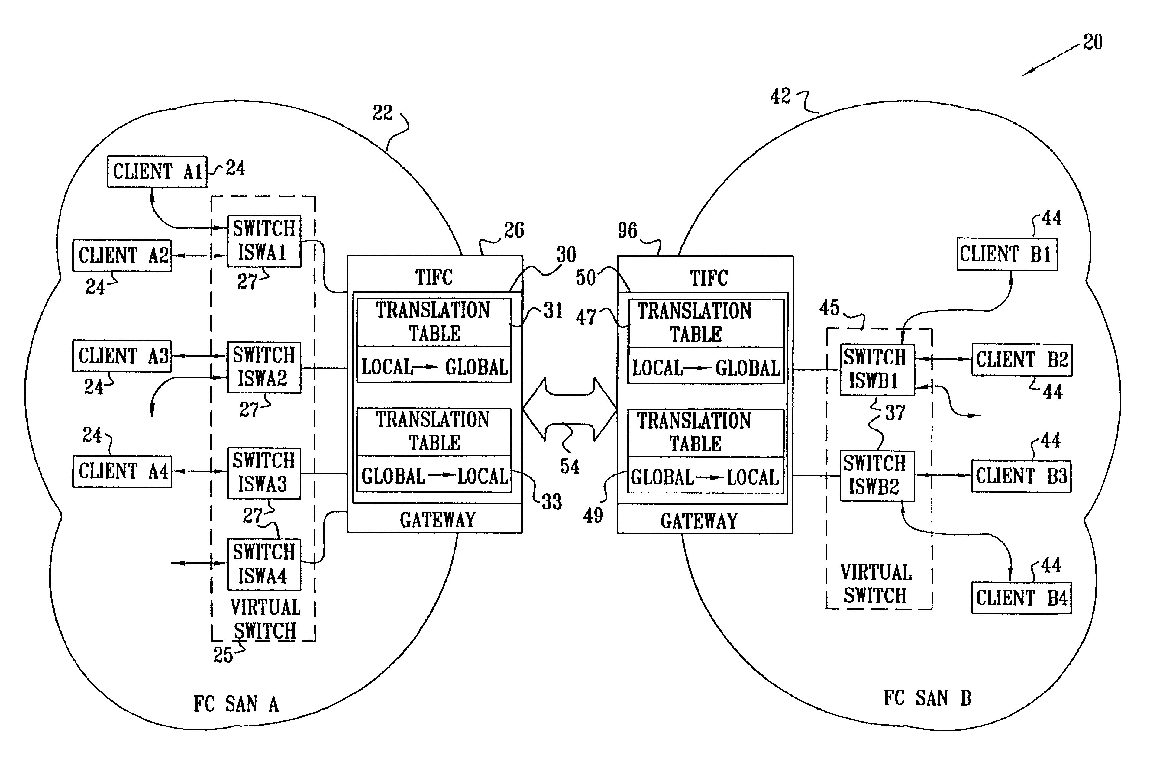
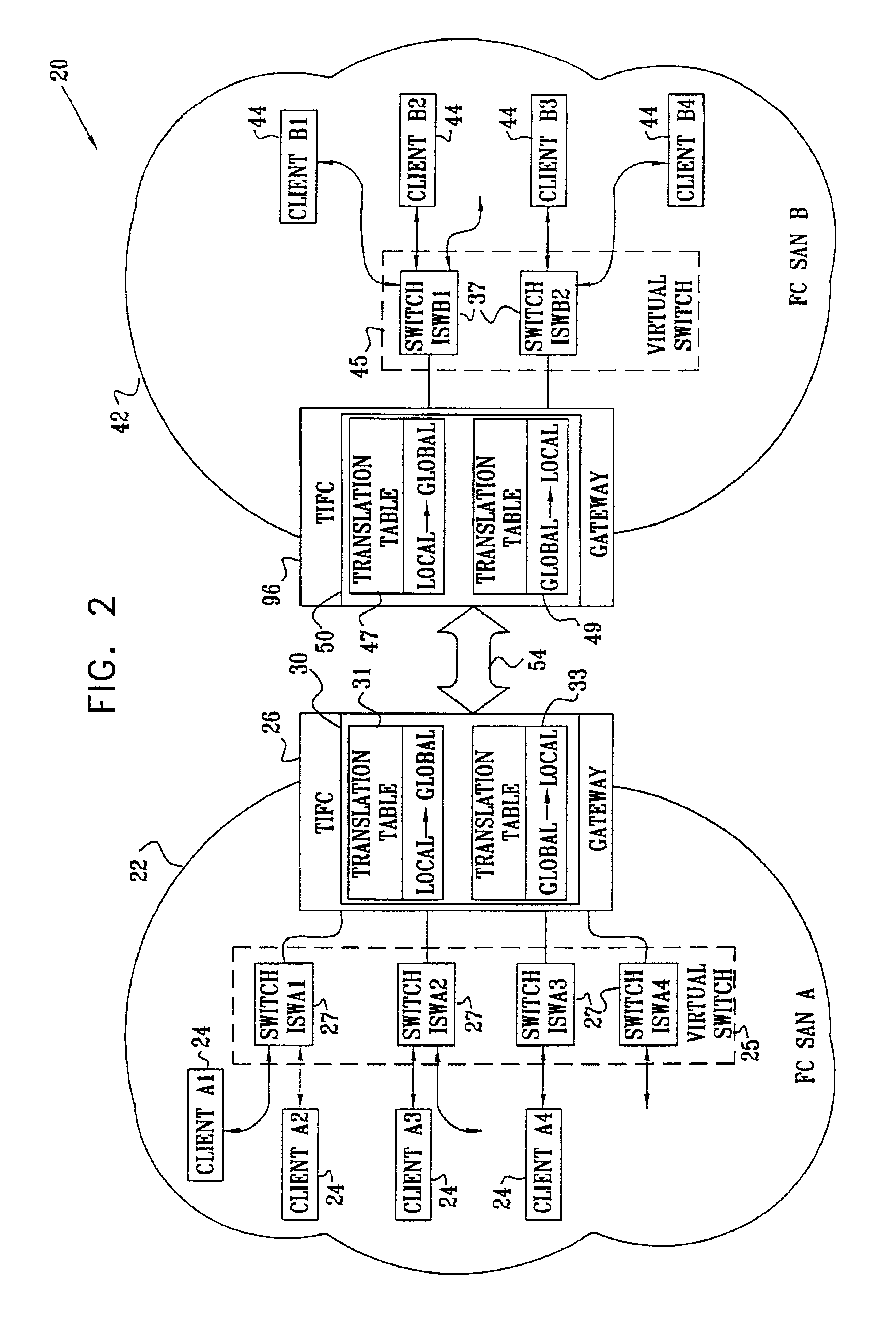
[0053]Reference is now made to FIG. 2, which is a schematic diagram of two Fibre Channel Storage area Networks coupled together as a compound Fibre Channel network system 20, according to a preferred embodiment of the present invention. In system 20 a Fibre Channel first Storage area Network 22, also herein termed FC SAN A, comprises a first plurality of generally similar internal switches 27 also termed herein switch ISWA1, switch ISWA2, . . . , which are coupled to transfer data between themselves. As described in more detail below, all internal switches 27 are grouped together as a virtual switch 25. FC SAN A also comprises a second plurality of generally similar clients 24, also termed herein client A1, client A2, . . . , each of which is coupled to one of switches 27. Clients 24 transfer data between themselves, via their respective switches, according to an industry standard Fibre Channel protocol, published by the American National Standards Institute. Each client 24 has a re...


PUM


Abstract

Apparatus for transferring data, including a first gateway, adapted to operate as a first switch in a first storage area network (SAN) operating according to a Fiber Channel protocol, and which is coupled to receive a data-frame addressed to a virtual address of a receiving client operative in a second SAN. The apparatus also includes a second gateway, adapted to operate as a second switch in the second SAN, which operates according to the Fiber Channel protocol substantially independently of the first SAN. The second gateway is coupled to receive the data-frame from the first gateway, and is adapted to look up a local address of the receiving client in the second SAN by using at least part of the virtual address as an index to an incoming-data-frame translation table, and to transmit the data-frame addressed to a local address of the receiving client.

Description

BACKGROUND OF THE INVENTION[0001]1. Field of the Invention[0002]The present invention relates generally to data transfer, and specifically to data transfer between separated networks operating according to a Fibre Channel protocol.[0003]2. Background Art[0004]Clients who are coupled within a storage area network (SAN) operating according to a Fibre Channel (FC) protocol, such as the FC-PH Fibre Channel protocol, issued by the American National Standards Institute, Washington, D.C., transfer data between themselves in the form of data-frames. Within the SAN, each client is coupled to an FC switch, and the protocol defines the form to which a header of the frame needs to conform. The header comprises a destination address of the client to whom the data-frame is being sent, and a source address of the transmitting client. The protocol requires that each client within the SAN has a unique address.[0005]FIG. 1 is a schematic diagram of an address structure 10 according to the Fibre Chann...

Claims


Application Information

Patent Timeline
IPC IPC(8): H04L12/28H04L29/06H04L29/08H04L29/12
CPCH04L29/12584H04L67/1097H04L61/2596H04L29/12801H04L61/6004H04L2101/604
Inventor CZEIGER, MOSHEFLINT, YOAVALEXANDROVICH, ILYAGISSIN, VICTOR
Owner CALLAHAN CELLULAR L L C
Why Eureka
Try Eureka