
Method and apparatus for edge correlation between design objects

a technology of design objects and edges, applied in the field of edge correlation between design objects, can solve the problems of voids, voids, voids, and spatial geometry, and cumbersome methods and painstaking detail, and achieve the effects of disrupting the entire model, rigid and often unforgiving interdependencies between edges, and voids, connections, and spatial geometry

Inactive Publication Date: 2006-01-10
PROFICIENCY
View PDF17 Cites 35 Cited by
  • Summary
  • Abstract
  • Description
  • Claims
  • Application Information

AI Technical Summary

Benefits of technology

"The patent describes a computer-based technique for aligning edges between different design objects in computer-aided design systems. The technique involves exporting a source edge from a source CAD system and importing it into a global scene. The global scene is then exported into a local scene, where non-overlapping edges are removed to create a correlated set of edges. This allows for design features, such as round or chamfer operations, to be performed on the correlated set of edges in the target CAD system. The technical effect of this patent is improved efficiency and accuracy in aligning edges between different design objects in computer-aided design systems."

Problems solved by technology

While this method is cumbersome and painstakingly detailed, it is often a preferred data entry paradigm for engineers who design complex free-form surfaces.
The strength of this paradigm is also its weakness: namely, the rigid and often unforgiving interdependencies between edges, connections, voids, and spatial geometry.
For instance, moving a single line or point can disrupt the entire model.
In a competitive system, however, more complex shapes may be modeled.
Not only are their methodologies secret, but the data structures that implement their methodologies are secret.
And herein lies a problem.
When the users of different CAD systems need to share design data they are currently able to do so only to a limited extent.
Typically the extent to which the users are able to share data is limited by the amount of co-operation between the various CAD vendors.
But the APIs are functionally limited and often have significant problems exchanging complex design features and / or information.
The problem is getting worse.
Consolidation in certain industries, such as the automotive and aircraft industries, creates more CAD data exchange problems.
But because of incompatible file types and differing computational and algorithmic methodologies, the CAD model cannot be provided.
Even worse, when Boeing decides to create design synergies between the two merged entities, the Boeing engineers and the McDonnell Douglas engineers might be completely unable to exchange complex CAD models.
Of course, the same is true of Ford Motor Company, which recently purchased Jaguar and Volvo. FIG. 3 diagrammatically presents the communication problem.
The economies of scale desired by the merger of such entities are victims of the inevitable battles over sharing information and know-how between the CAD vendors.
Moreover, the collaboration between engineers from separate entities (i.e., between original equipment manufacturers and first and second tier suppliers), under the current state-of-the-art, will be all but impossible—as engineers waste time and money desperately trying to share design files made from disparate CAD systems.
While standards may exist for exchanging raw data images (e.g., TIFF and JPEG) and boundary representations (e.g., IGES and STEP), these standards do not preserve the design intent of the engineer.

Method used


Image

  • Method and apparatus for edge correlation between design objects
  • Method and apparatus for edge correlation between design objects
  • Method and apparatus for edge correlation between design objects

Examples


Embodiment Construction

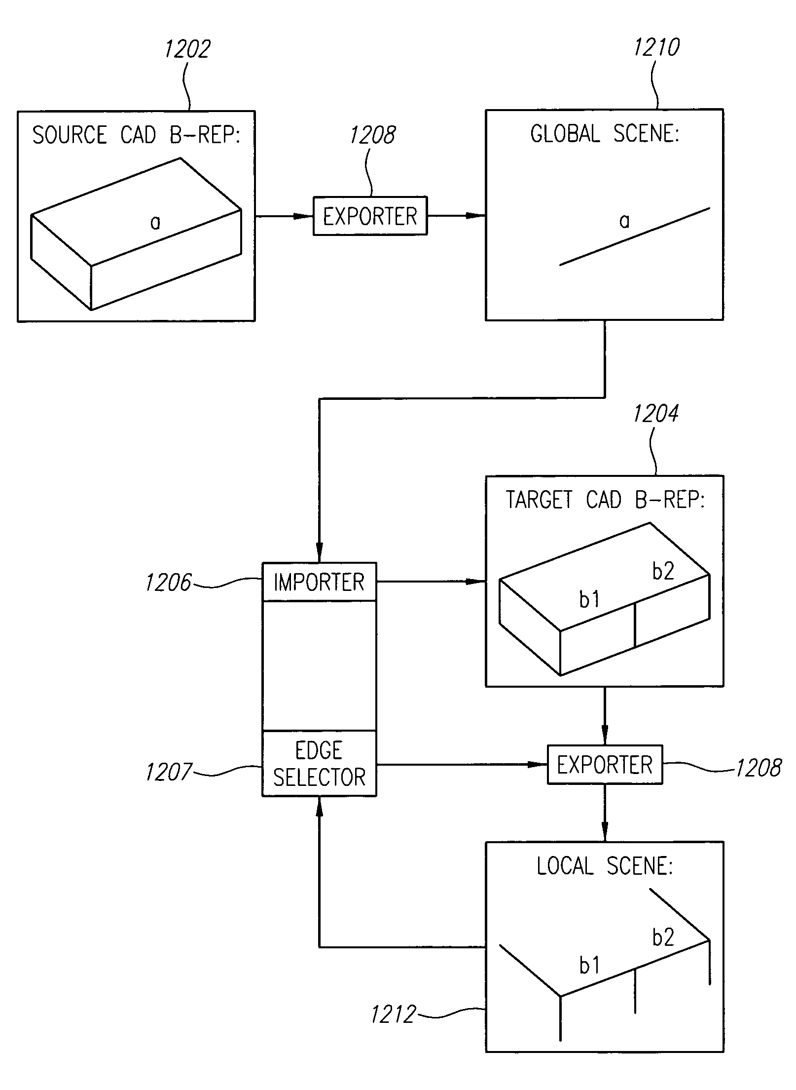
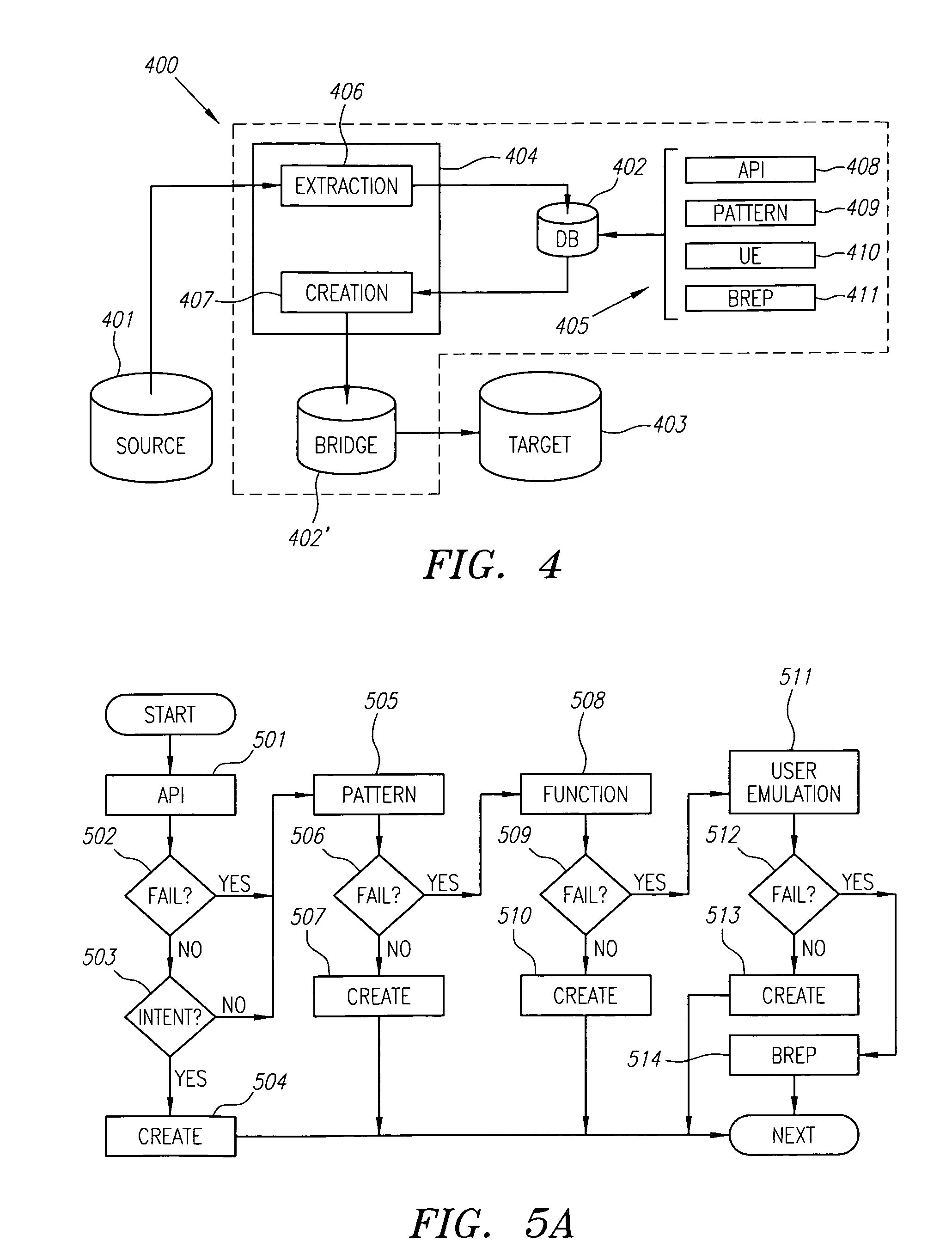
[0029]FIG. 4 is a conceptual drawing of an embodiment of the invention. The invention includes a method and system for exchanging computer aided design data from a source computer system 401 to a target computer system 403. Both the source and target computer systems are used in a computer aided design environment. According to one embodiment, an intermediate system 400 provides the functionality to make the conversion from the source 401 to the target 403 systems. An execution area 404 performs two basic functions. First, the execution area 404 extracts CAD data from the source 401. Second, the execution area creates CAD data that can be used by the target 403. In one embodiment, a database 402 provides a knowledge catalogue 405 of operations that can be performed in either the source 401 or target systems to extract and create the CAD data. Included in the knowledge catalogue 405 are a sequence of operations that are used for the conversion processes, the operations including an a...


PUM


Abstract

Computer implemented techniques for edge correlation between design objects in computer-aided design systems are provided. According to one embodiment, a source edge is exported from a source CAD system into a data representation in a global scene. The global scene is imported into a target CAD system so that one or more candidate target edges can be identified. Once the candidate target edges are identified, they are exported into a data representation of a local scene. Through a series of techniques, which can include an edge overlap algorithm, a region containment algorithm, an edge containment algorithm, and an edge extension algorithm, non-overlapping candidate target edges are removed from the local scene until a correlated set of target edges is produced. Design features, such a round or chamfer operation, can then be performed in the target CAD system on the correlated set of edges, just as they are in the source CAD system.

Description

CROSS-REFERENCE TO RELATED APPLICATIONS[0001]This application is related to U.S. patent application Ser. No. 09 / 655,540, entitled “DATA EXCHANGE BETWEEN COMPUTER AIDED DESIGN SYSTEMS”, Ser. No. 09 / 655,546, entitled “USER EMULATION FOR COMPUTER AIDED DESIGN DATA EXCHANGE”, Ser. No. 09 / 660,426, entitled “PATTERN MATCHING FOR DATA EXCHANGE BETWEEN COMPUTER AIDED DESIGN SYSTEMS” now U.S. Pat. No. 6,828,963, and PCT International Application Serial No. PCT / US00 / 24446, entitled “METHOD AND APPARATUS FOR EDGE CORRELATION BETWEEN DESIGN OBJECTS”, all filed Sep. 6, 2000. This application is also related to U.S. patent application Ser. No. 09 / 391,311, filed Sep. 7, 1999, entitled, “METHOD AND SYSTEM FOR THE EXCHANGE OF CAD DATA” now U.S. Pat. No. 6,614,430, and U.S. Provisional Application Ser. No. 60 / 099,340, filed Sep. 8, 1998, entitled, “DATA EXCHANGE IN MECHANICAL COMPUTER-AIDED DESIGN”. All of these applications are incorporated herein by reference in their entirety.BACKGROUND[0002]1. Fi...

Claims


Application Information

Patent Timeline
Patent Type & Authority Patents(United States)
IPC IPC(8): G06F17/50G06F19/00
CPCG06T17/10Y10S706/919Y10S715/964
Inventor ETZION, MICHALSPITZ, STEVEN
Owner PROFICIENCY
Learn More