Method and apparatus for anchoring a mine roof bolt

a technology of mine roof and bolt, which is applied in the field of apparatus and methods for anchoring devices in rock material, can solve the problems of inability to achieve complete mechanical engagement before the adhesive sets, inability to fully engage the mechanical components, and inability to meet the requirements of the construction process, so as to achieve a simple and convenient design. the effect of mechanical anchor

Inactive Publication Date: 2006-01-17
ROBERTSON JR ROY LEE
View PDF24 Cites 17 Cited by
  • Summary
  • Abstract
  • Description
  • Claims
  • Application Information

AI Technical Summary

Benefits of technology

[0016]The present invention is an improved mine roof bolt having a main bolt shaft with a threaded end, a fixed camming nut, and threaded expansion shell. It has a more easily activated mechanical anchor and an overall simpler design than the prior art.
[0017]Accordingly, it is a primary objective of this invention to improve mine safety by decreasing the rate of occurrence of “spinners” in mine roof bolts.
[0019]It is also an objective of this invention to provide a mine roof bolt that is easier to anchor in a receiving bolt hole.
[0021]It is a still further objective to provide a mine roof bolt which decreases the occurrence of twisting of the expansion shell.

Problems solved by technology

A mine shaft itself may cause fractures and weaknesses in a strata in its ceiling, or it may just expose an inherently weak and unstable layer.
Obtaining complete mechanical engagement before the adhesive sets is very time dependent.
Variations in the mechanical components, in particular, may prove problematic.
However, the adhesive anchor is lost and it is the adhesive anchor that provides the majority of the long term strength of the anchoring system.
This is particularly dangerous since the bolt appears to be anchored, but the superior long term anchor of the adhesive component has been lost.
However, the actual result is a “spinner”.
This, too, is a problem.
The mechanical anchor may widen the hole as it turns and fail to pull tight within the hole.
If it continues to turn in a loosened hole, again, the adhesive is at risk.
Another problem is more specific to the mechanical elements of the anchoring systems that use expansion shells having the tapered wedge fingers joined by a common ring at the base with a camming nut being drawn into the expansion shell.
Again, this substantially decreases the overall holding power of the bolt, allowing ceiling collapses where the load exceeds the strength of the anchor.

Method used


Image

  • Method and apparatus for anchoring a mine roof bolt
  • Method and apparatus for anchoring a mine roof bolt
  • Method and apparatus for anchoring a mine roof bolt

Examples


Embodiment Construction

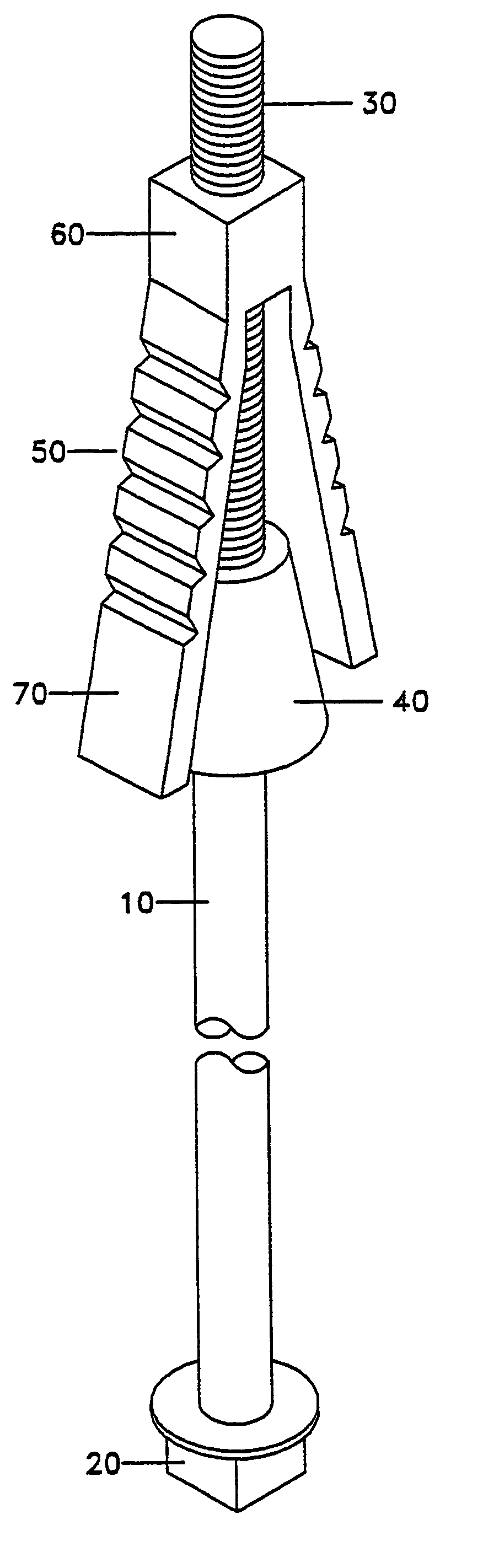
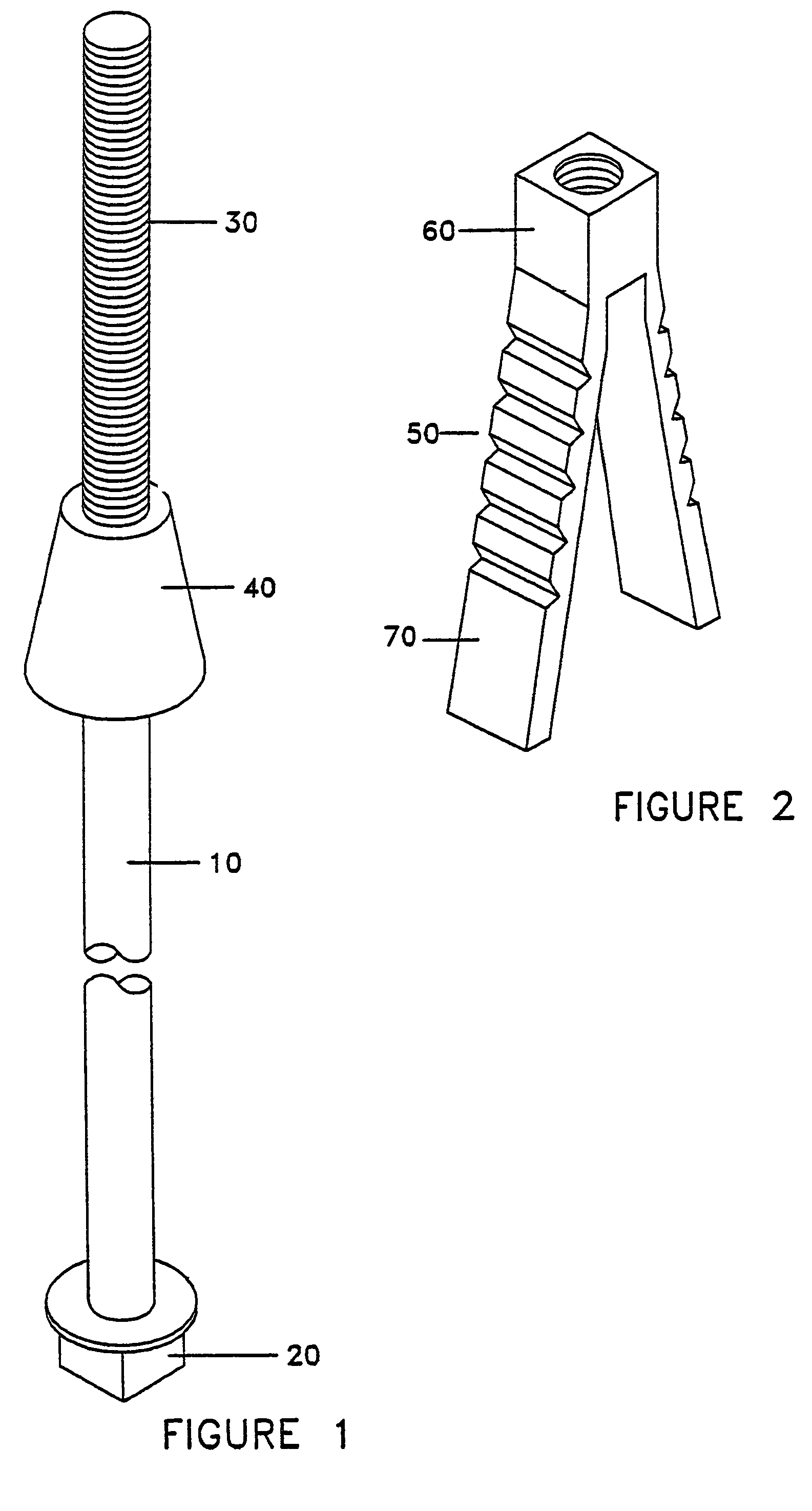
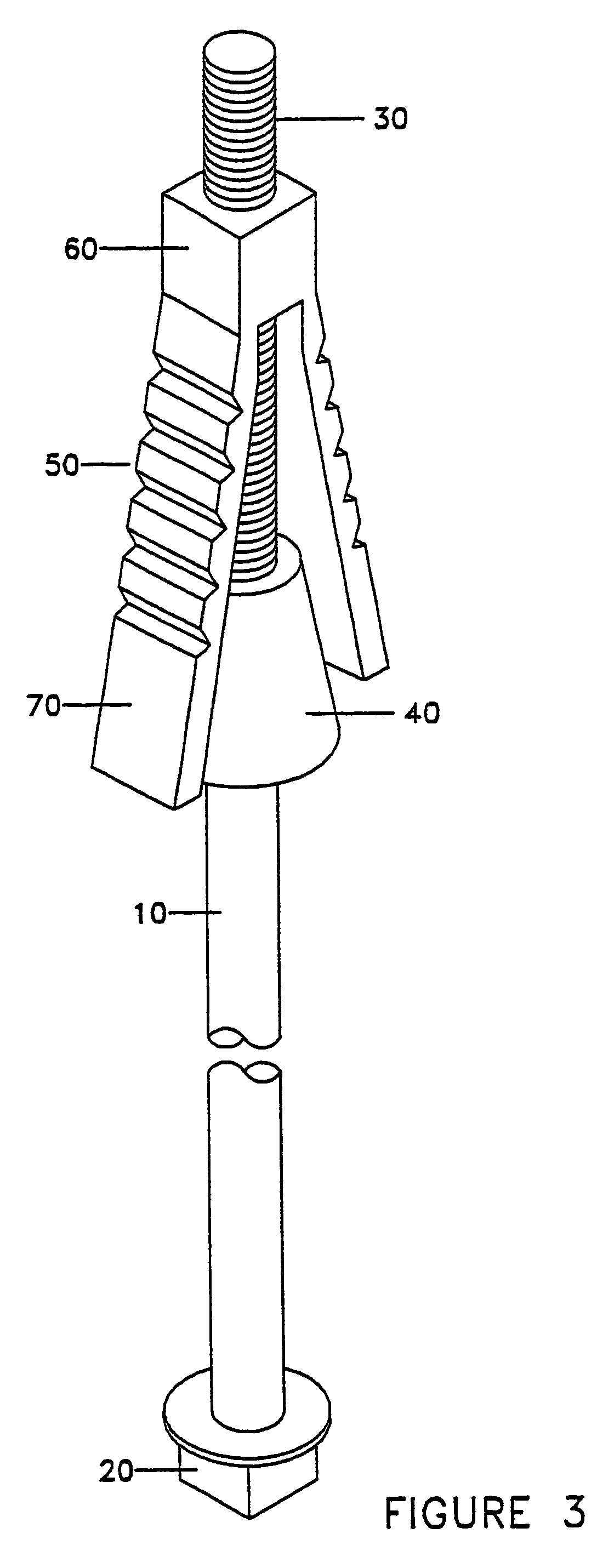
[0046]The following discussion illustrates only some of the possible configurations claimed in this invention and should not be interpreted as limiting the scope of the claims. FIG. 1 depicts the bolt portion (10) of the mechanical anchoring system. The bolt has a means for turning it (20) via a driver or wrench on one end, machine threads (30) on the other end, and a camming nut (40) fixed on the shaft of the bolt (10) at a position nearer to the machine threads (30). FIG. 2 shows an expansion shell (50) having as its central component a threaded nut portion (60), and at least two, in this case two, wedge fingers (70) extending from the threaded nut portion (60) in a direction essentially parallel to the axis of the hole through the threaded nut portion (60). FIG. 3 shows the expansion shell (50) threaded onto the machine threads (30) of the bolt portion (10) with the wedge fingers (70) directed towards the camming nut (40).

[0047]To use the bolt assembly (80), it is inserted into a...


PUM


Abstract

An improved mine roof bolt is disclosed. The mine roof bolt comprises a bolt portion having a camming nut rigidly fixed to it and a threaded end and an expansion shell having a central threaded nut with wedge fingers extending from it. The expansion shell is threaded onto the threaded section of the bolt. Turning the bolt while it is in a hole causes the expansion shell to move along the bolt and brings the wedge fingers into contact with the camming nut, spreading the wedge fingers into contact with the hole sides. As the turning of the bolt continues, the relative movement of the camming nut and wedge fingers increases the wedging effect within the hole until the bolt is anchored in the hole. While turning of the bolt may serve to mix a catalytic adhesive, the adhesive is not needed to activate the mechanical anchoring mechanism of the mine roof bolt.

Description

BACKGROUND OF THE INVENTION[0001]1. Field of the Invention[0002]This invention relates generally to an apparatus and method for anchoring devices in rock material. More specifically, it relates to mine roof bolts and methods of using them to support the rock layer exposed in mine roofs by drilling holes in the roofs and mechanically and adhesively anchoring the bolts to higher layers of rock.[0003]2. Description of the Related Art[0004]Mine shafts sometimes experience cave-ins, collapses, or falling rock due to the layered and stratified makeup of the earth. A mine shaft itself may cause fractures and weaknesses in a strata in its ceiling, or it may just expose an inherently weak and unstable layer. To assist in preserving the integrity of the ceiling, it is common to support the ceiling with bolts anchored up into rock layers above the ceiling. Plates between the bolt heads on the exposed ends of the bolts and the ceilings are used to transfer force from the anchored bolts to the e...

Claims


Application Information

Patent Timeline
Patent Type & Authority Patents(United States)
IPC IPC(8): E21D21/00
CPCE21D21/008
Inventor ROBERTSON, JR., ROY LEE
Owner ROBERTSON JR ROY LEE
Why Eureka
Try Eureka