Load change safety system

a safety system and load change technology, applied in the direction of mechanical conveyors, thin material processing, article separation, etc., can solve the problems of not meeting the guidelines of international safety standards such as redundancy and self-testing, and requiring too much recovery time to use as a safety solution,

Active Publication Date: 2006-01-17
GEO M MARTIN
View PDF22 Cites 17 Cited by
  • Summary
  • Abstract
  • Description
  • Claims
  • Application Information

AI Technical Summary

Benefits of technology

[0015]The Load Change Safety System 1–1″″ of the present invention is a safety system to keep the operator 30 a safe distance from the variable pinch point gap 9,9′ while the sheet stacker 2,2′ is performing the load change cycle 56, hence achieving the very important objective of keeping the operator 30 from accidentally getting near or in the variable pinch point gap 9,9′ while decreasing.
[0017]A further objective of the present invention is to provide the ability to perform self-testing on the hydraulic system by adding feedback sensors 18,19 to allow detection of a hydraulic leak and / or failure.
[0019]A further objective of the present invention is to define a configuration of a light guard system 27 by which the optical repeating node 24′ on the operator side of the sheet stacker 2,2′ near the discharge end 4,4′ of the stacking deck 3,3′ is part of a movable remote control mean 35 in order to reduce the interference that would be caused if a floor mounted optical repeating node 24 was located in the same general proximity.

Problems solved by technology

This rapid motion of the stacking deck 3 and / or sheet material removal system 7′ to within close proximity results in a hazardous condition where the variable pinch point gap 9,9′ is formed between the bottom side of the discharge end 4,4′ of the stacking deck 3,3′ and the sheet material removal system floor conveyor or bundle takeaway system.
Due to the weight and strength of the machinery, a person caught in this variable pinch point gap 9,9′ may have the result of serious injuries or death.
These procedures require too much recovery time to use as a safety solution during production operations.
Even if this does not hinder the productivity due to the configuration of the sheet stacker 2,2′ production line, this solution still may not meet the guidelines of the International Safety Standards which include redundancy and self-testing.
However, this system has many short comings including 1) lack of a failsafe mode should a single component fail, 2) no self testing, 3) difficult installation and maintenance due to stringent mirror alignment requirements, 4) lack of flexibility when needing multiple mirrors to reflect the light, 5) no fault detection of cross talk from external optical sources, 6) interference due to light stand locations and 7) not able to run fully automatic cycling of full stacks 52 when the sheet stacker 2,2′ is equipped with an automatic dunnage 50 and / or pallet 51 system.

Method used


Image

  • Load change safety system
  • Load change safety system
  • Load change safety system

Examples


Embodiment Construction

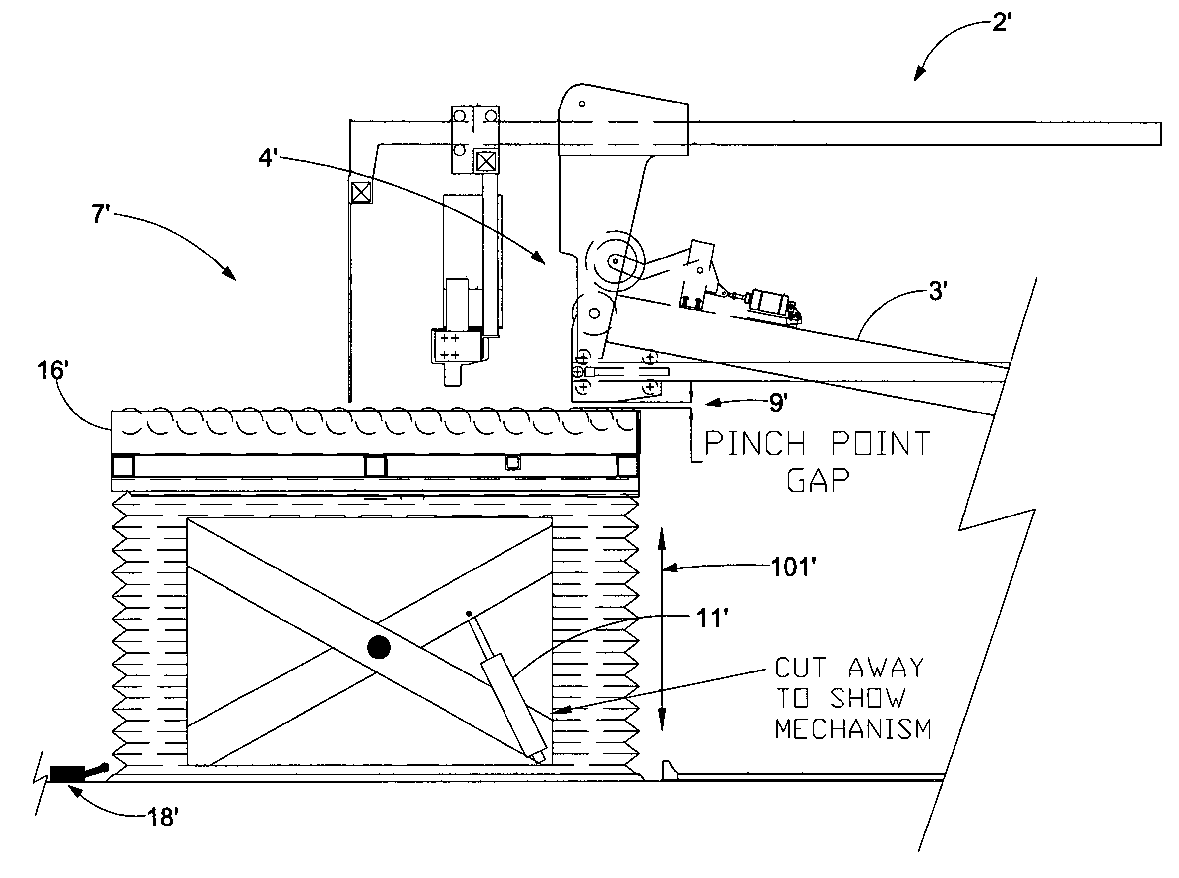
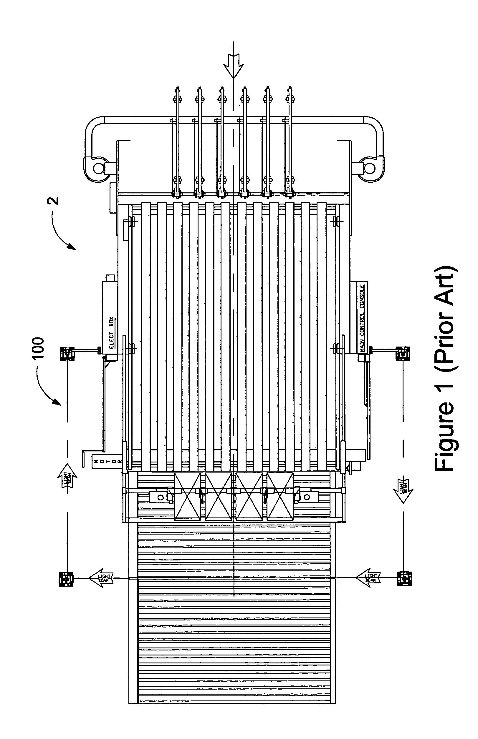
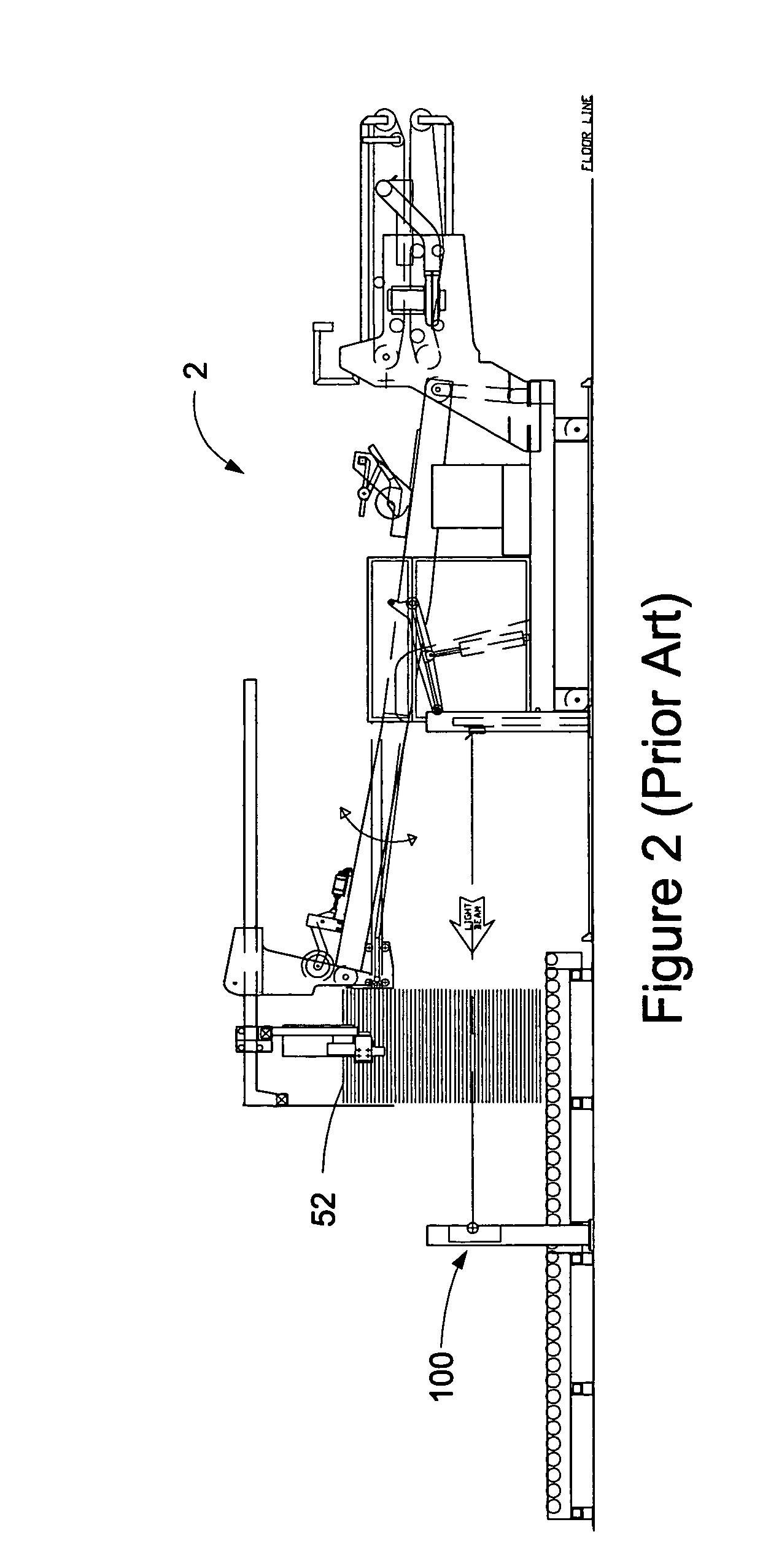
[0062]In the present invention, a load change safety system 1–1′″ is provided for a sheet stacker 2,2′ in which a variable pinch point gap 9,9′ is created during the load change cycle 56 due to the motion of the stacking deck 3,3′ and / or the conveying sheet material removal system 7,7′. The variable pinch point gap 9 can be created with an “upstacker” type of sheet stacker 2 where the stacking deck 3 moves in a generally upward direction, while the conveying sheet removal system 7 remains fixed, as illustrated in FIGS. 5, 6, 7&8. Alternatively, the variable pinch point gap 9′ can be created with a “downstacker” type of sheet stacker 2′ where the stacking deck 3′ remains fixed, while the conveying sheet removal system moves in a generally downward direction, as illustrated in FIGS. 9, 10, 11&12.

[0063]The sheet stacks 6 are first created as the sheet material 5 exits the discharge end 4,4′ of the stacking deck 3,3′ and the variable pinch point gap 9,9′ increases. This increase in said...


PUM


Abstract

A load change safety system in which a sheet stacker having a stacking deck formed with a discharge end discharges sheet material onto and builds a sheet stack on a conveying sheet stack removal system formed with a receiving means. A variable pinch point gap is formed by relative motion between the discharge end of the stacking deck and the receiving means of the conveying sheet material removal system. The safety system includes redundant means selectively preventing a decrease in the variable pinch point gap. The redundant means of the safety system preferably includes an electro-optical light guard means operably connected to the redundant means with one or more redirections of light beams to create a light guard perimeter guarding portions of the stacker and sheet removal system to guard against access to the pinch point.

Description

[0001]This invention relates to a system designed to keep the operator 30 and / or other individuals safe from the hazardous condition of a lowering stacking deck 3,3′ of a sheet stacker 2,2′. The hazardous condition is the variable pinch point gap 9,9′ created between the discharge end 4,4′ of the stacking deck 3,3′ and a conveying sheet material removal system 7,7′ typically located under the discharge end 4,4′ of the sheet stacker 2,2′. The conveyor system provides means for transporting material away from the sheet stacker 2,2′. The need for the load change safety system 1–1″″ is amplified by the fact that the operator 30 and / or other individuals are required to frequently go near the hazardous area of the variable pinch point gap 9,9′ during normal production operation to place protective sheets, referred to as dunnage 50 and / or pallets 51 on the conveying sheet material removal system 7,7′ before each sheet stack 6 is created at the discharge end 4,4′ of the sheet stacker 2,2′.[...

Claims


Application Information

Patent Timeline
Patent Type & Authority Patents(United States)
IPC IPC(8): B65G57/00B65H29/50B65H29/66
CPCB65H29/50B65H29/66B65H2407/10B65H2701/1762
Inventor TALKEN, DANIEL J.RIZZUTI, CHARLES D.
Owner GEO M MARTIN
Why Eureka
Try Eureka