Polarized semi-active laser last pulse logic seeker using a staring focal plane array

a logic seeker and semi-active laser technology, applied in the field of missiles, can solve the problems of difficult common name “clutter”, and difficulty in detecting background and/or jamming radiation, and achieve the effect of reducing the difficulty of target acquisition and tracking

Inactive Publication Date: 2006-01-17
UNITED STATES OF AMERICA THE AS REPRESENTED BY THE SEC OF THE ARMY
View PDF9 Cites 25 Cited by
  • Summary
  • Abstract
  • Description
  • Claims
  • Application Information

AI Technical Summary

Problems solved by technology

A weakness in the system described in the '241 patent is that the temporal and spatial laser returns (e.g. laser energy reflected, or scattered, from the laser-illuminated target) are often difficult to distinguish from background and / or jamming radiation, commonly called “clutter”, existing at or near the target location.
Clutter interferes with the temporal and spatial laser returns and renders target acquisition and tracking difficult.
A relatively new and slowly maturing technology, infrared polarimetry is limited by polarization aberrations, scattering and birefringence effects introduced by extant instrumentation.
As described in the '345 patent, infrared polarimetry can be used to enhance the discrimination of targets from clutter, but use has been limited to conventional forward looking infrared (FLIR) camera systems, such as those produced by FLIR Systems of Boston, Mass.

Method used


Image

  • Polarized semi-active laser last pulse logic seeker using a staring focal plane array
  • Polarized semi-active laser last pulse logic seeker using a staring focal plane array
  • Polarized semi-active laser last pulse logic seeker using a staring focal plane array

Examples


Embodiment Construction

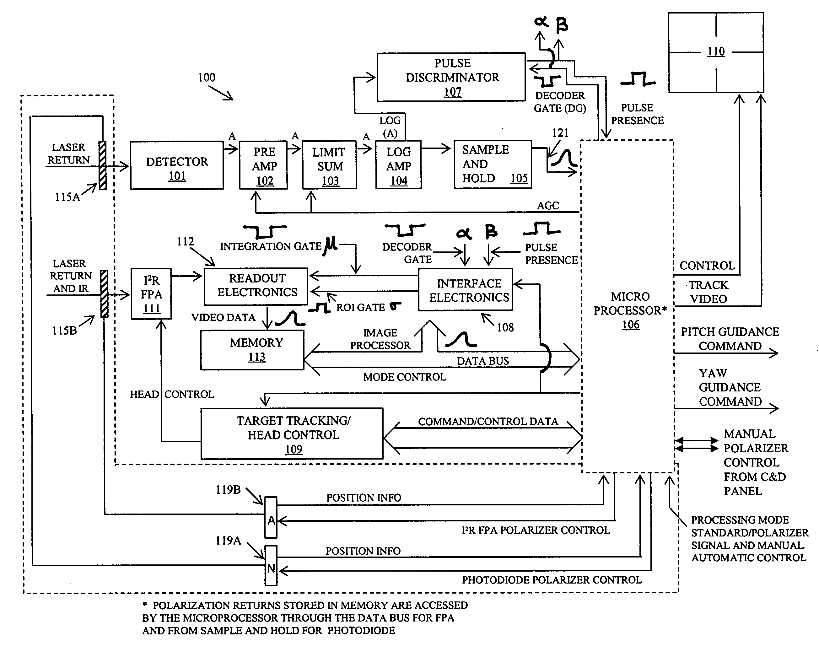
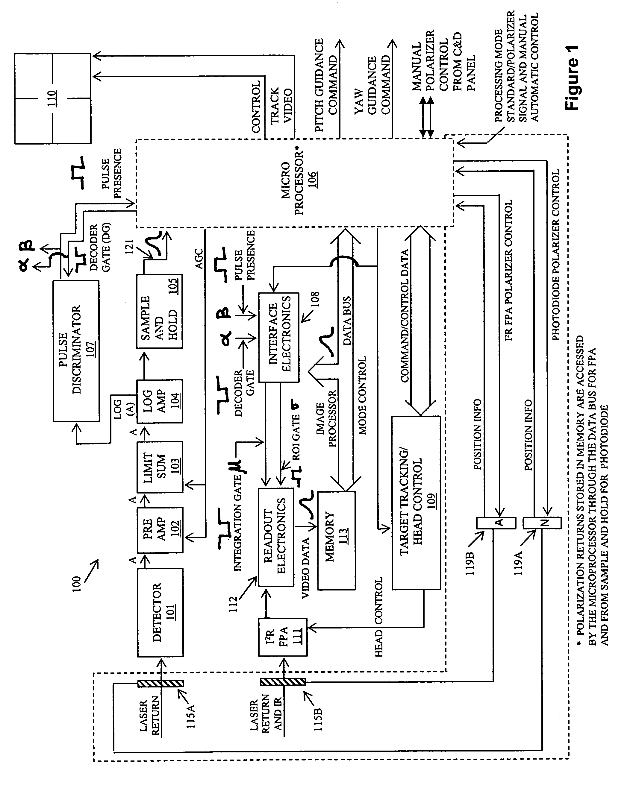
[0013]FIG. 1 illustrates one embodiment of an improved SALLPL missile seeker 100, wherein the improvement is included within the dashed lines. In an illustrative embodiment, the improvement is achieved by movably disposing polarizers 115A and 115B in front of PIN photodiode detector 101 and staring imaging infrared focal plane array 111, respectively. In one example, polarizer 115A is disposed in, and completely covers, the PIN photodiode detector's field of view. Similarly, polarizer 115B is disposed in, and completely covers, the field of view of the staring imaging infrared focal plane array 111.

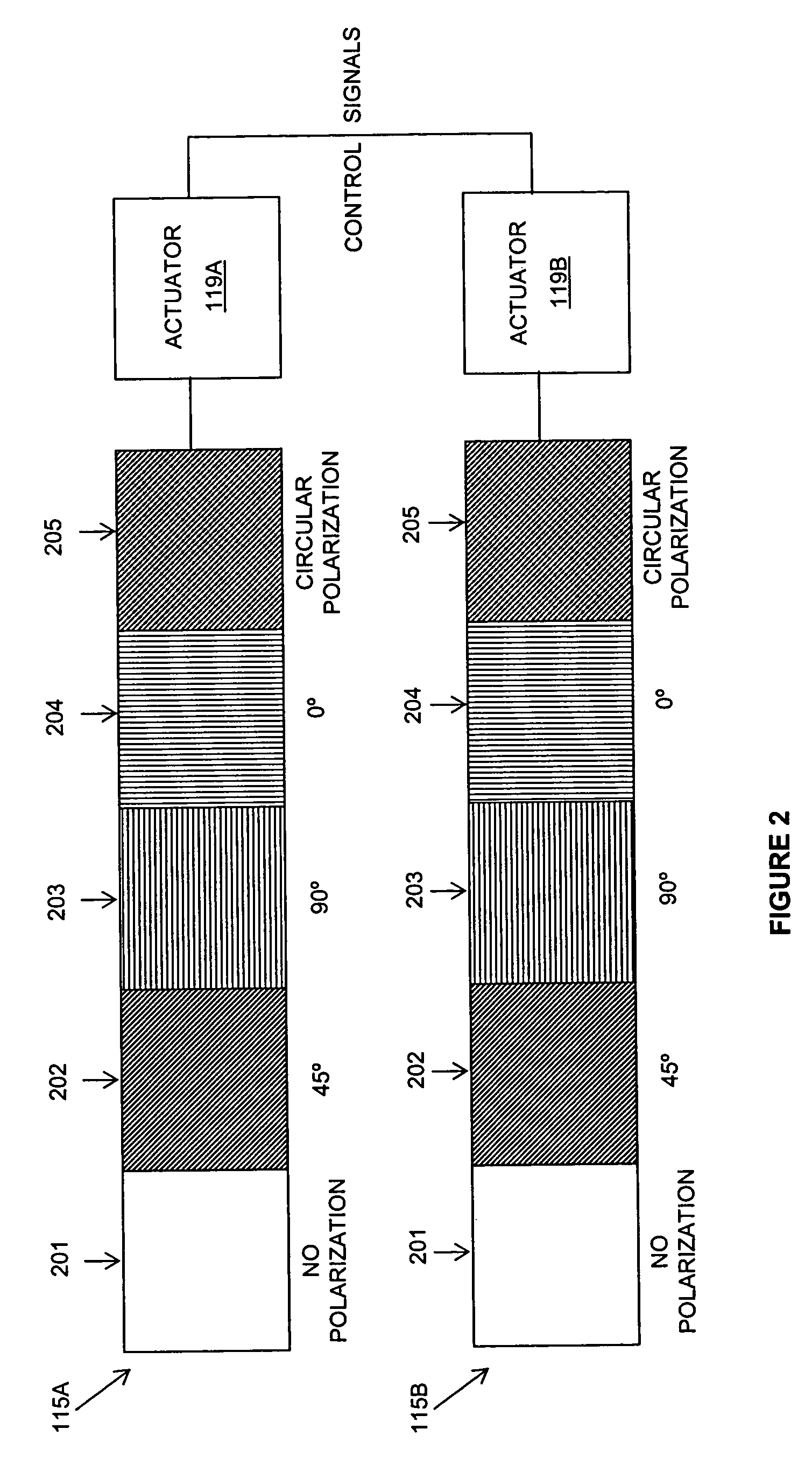
[0014]Actuator 119A is connected to the polarizer 115A and, and via a control channel, to the microprocessor 106. Actuator 119B is connected to the polarizer 115B and, via a control channel, to the microprocessor 106.

[0015]FIG. 2 is a schematic depiction of the polarization-actuator assemblies. In the embodiment shown, they are identical in configuration, but not necessarily of the same s...


PUM

PropertyMeasurementUnit
polarization angleaaaaaaaaaa

Abstract

An improvement in a semi-active laser last pulse logic missile seeker is disclosed and claimed. In one embodiment, the improvement includes a first polarizer disposed in the detection field of view of the PIN photodiode detector and a second polarizer disposed in the detection field of view of the staring imaging infrared focal plane array. Each of the first and second polarizers has an identically configured plurality of segments. Each segment allows transmission of a different polarization than other segments and is sized to completely cover the fields of view of both the PIN photodiode detector and the staring imaging infrared focal plane array. First and second actuators are connected to the first and second polarizers, respectively, to synchronously and simultaneously step identical and corresponding segments in a plurality of discrete steps within the fields of view in response to incoming temporal and spatial laser returns.

Description

DEDICATORY CLAUSE[0001]The invention described herein may be manufactured, used and licensed by or for the Government for governmental purposes without the payment to us of any royalties thereon.BACKGROUND[0002]The invention relates to missiles generally, and more particularly, to a polarized semi-active laser last pulse logic missile seeker.[0003]Conventional semi-active laser last pulse logic (SALLPL) missile seekers, staring imaging infrared (I2R) focal plane arrays, and their use together to detect and track missile targets, are known in the art. For example, U.S. Pat. No. 6,111,241 ('241 patent), issued to English et al., sets forth and describes combining semi-active laser last pulse logic signal processing using a single PIN photodiode with a staring imaging infrared focal plane array to effectuate a more accurate and direct impact of a Hellfire missile on a laser-illuminated target.[0004]A weakness in the system described in the '241 patent is that the temporal and spatial l...

Claims


Application Information

Patent Timeline
Patent Type & Authority Patents(United States)
IPC IPC(8): G01C21/24G01C21/00G02F1/01G01J1/20G01J4/00G01S7/486G01S7/499G01S17/10G01S17/89
CPCG01J4/00G01S7/486G01S7/499F41G7/2293F41G7/008F41G7/2253F41G7/226G01S17/89G01S17/10
Inventor ENGLISH, JAMES E.PITTMAN, WILLIAM C.
Owner UNITED STATES OF AMERICA THE AS REPRESENTED BY THE SEC OF THE ARMY
Why Eureka
Try Eureka