Current feed circuit for sensor coils in coordinate input device

a technology of coordinate input device and current feed circuit, which is applied in the direction of oscillator, pulse technique, instruments, etc., can solve the problems of voltage loss, power loss, undetectable decrease of transmitted current, etc., and achieve the effect of stabilizing the output voltage at a certain level

Active Publication Date: 2006-01-17
WACOM CO LTD
View PDF2 Cites 5 Cited by
  • Summary
  • Abstract
  • Description
  • Claims
  • Application Information

AI Technical Summary

Benefits of technology

[0015]Cascade-connecting the plurality of driver transistors to the output of the high-frequency signal transmitting circuit can avoid the state in which the high-frequency signal transmitting circuit directly drives the sensor coils serving as the load thereof, thereby stabilizing the output voltage at a certain l

Problems solved by technology

Accordingly, power loss results due to voltage loss by on-resistance of the analog switches.
Thus, the transmitted current undesirably decreases.
Under low power supply voltage, insufficient transmitted current may result in serious problems.
The stray capacitance 160 of the s

Method used


Image

  • Current feed circuit for sensor coils in coordinate input device
  • Current feed circuit for sensor coils in coordinate input device
  • Current feed circuit for sensor coils in coordinate input device

Examples


Embodiment Construction

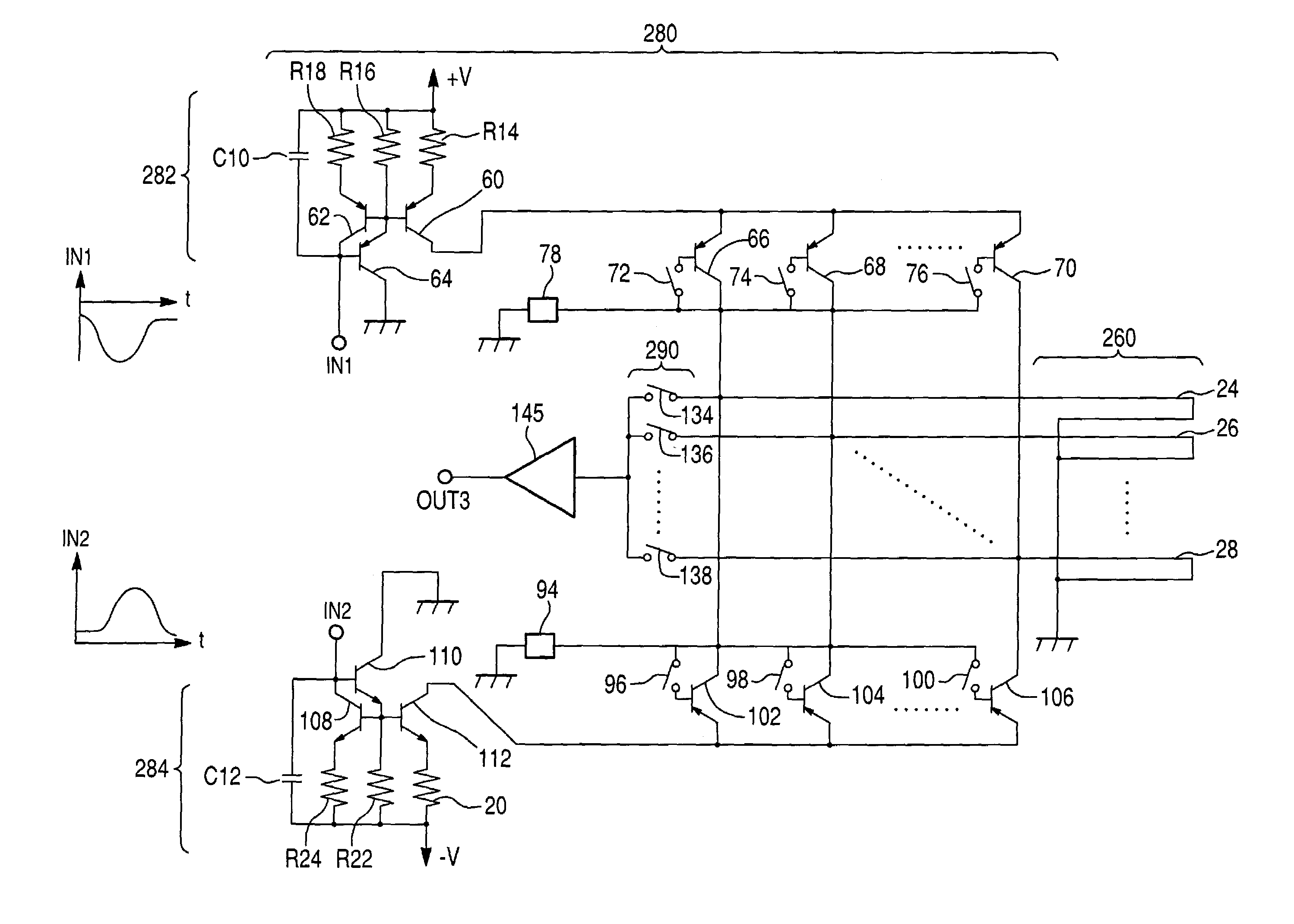
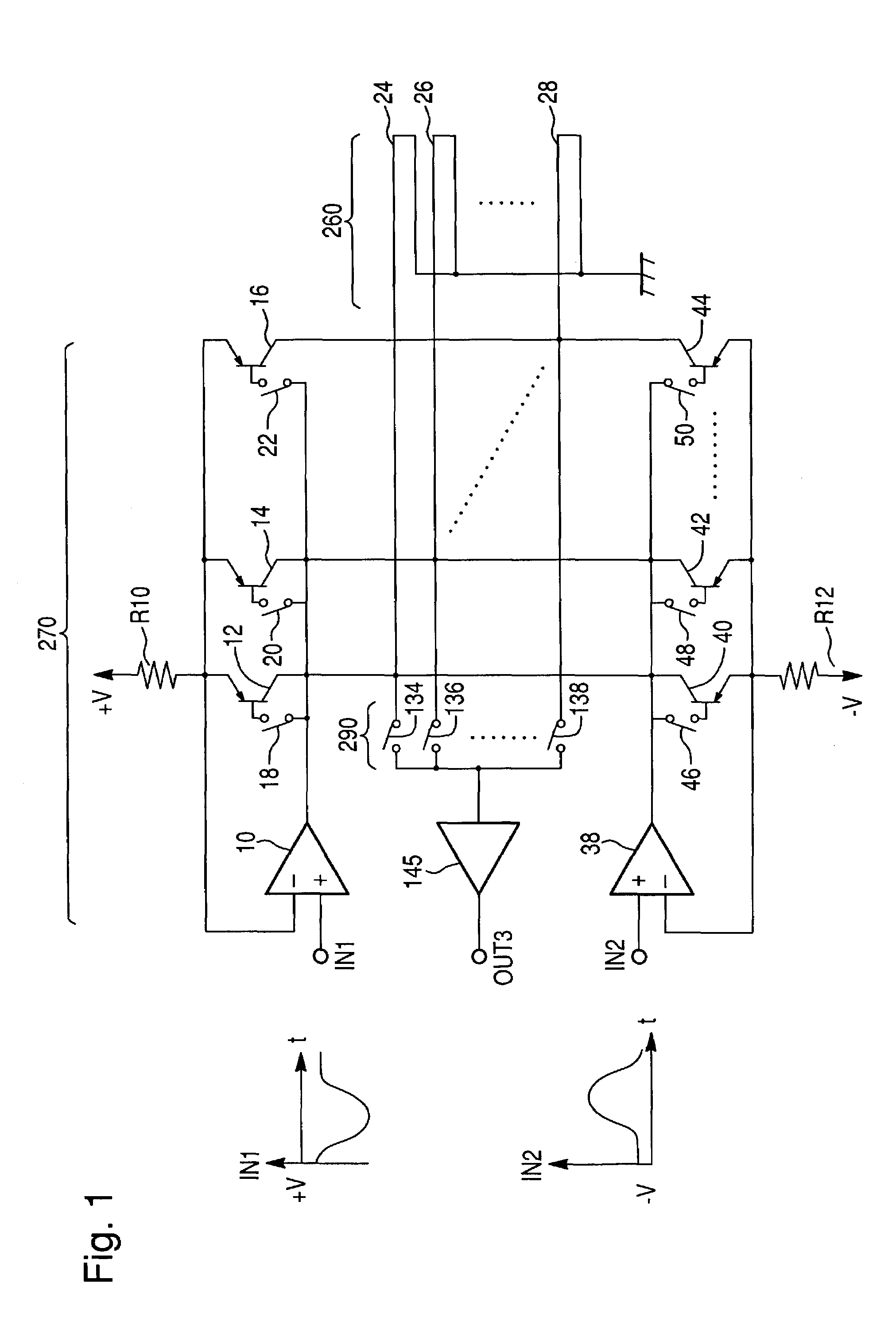
[0021]A circuit diagram according to a first embodiment of the present invention is best shown in FIG. 1. A transmitting circuit 270 includes a current feed circuit for feeding current to sensor coils in a coordinate input device. A sensor coil group 260 includes a plurality of sensor coils 24, 26 . . . 28 connected to the transmitting circuit 270. The transmitting circuit 270 also includes a high-frequency signal generator and a separation circuit in a transmitting circuit (the high-frequency signal generator, the separation circuit, and the transmitting circuit are the same as the high-frequency signal generator 121, the separation circuit 150, and the transmitting circuit 220 in FIG. 4)(not shown). FIG. 1 shows only downstream components from an op-amp 10 to which negative half-wave signals are supplied and an op-amp 38 to which positive half-wave signals are supplied.

[0022]As best shown in FIG. 1, the transmitting circuit 270 includes the current feed circuit for sensor coils fu...


PUM


Abstract

A current feed circuit for feeding a high-frequency current to a plurality of sensor coils in a coordinate input device includes a high-frequency signal transmitting circuit for generating a high-frequency current corresponding to a high-frequency signal input; a plurality of driver transistors, each being provided between the high-frequency signal transmitting circuit and each of a plurality of sensor coils for transmitting the high-frequency current to the corresponding sensor coil; and a plurality of switches, each being provided with respect to each of the plurality of driver transistors for turning on/off the corresponding driver transistor.

Description

CLAIM TO PRIORITY[0001]Applicant hereby claims priority under 35 U.S.C. § 119 to Japanese Application No. 2002-001952, filed Jan. 9, 2002, titled Current Feed Circuit for Sensor Coils in Coordinate Input Device, the disclosure of which is incorporated herein by reference.FIELD OF THE INVENTION[0002]The present invention relates to a current feed circuit for sensor coils in an electromagnetic inductive coordinate input device.BACKGROUND OF THE INVENTION[0003]The configuration of a conventional coordinate input device having a cordless position pointing device 200 is best shown in FIG. 3. Such a coordinate input device employs an electromagnetic transfer method, and has a plurality of sensor coils provided side by side in the direction of the X axis, as well as in the direction of the Y axis, of a coordinate input surface. An alternating magnetic field is transmitted from the sensor coils by feeding current to the sensor coils in a sending mode. When the transmitted alternating magnet...

Claims


Application Information

Patent Timeline
IPC IPC(8): G09G5/00G06F3/046G06F3/033G06F3/041
CPCG06F3/046
Inventor ODA, YASUO
Owner WACOM CO LTD
Why Eureka
Try Eureka