Shoe having an inflatable bladder

a technology of inflatable bladder and shoe, which is applied in the field of athletic shoes, can solve the problems of difficult to wear shoes for prolonged periods of time, pressure on the instep of the foot, and similar length feet without the same geometry, and achieve the effect of reducing the amount of air

Inactive Publication Date: 2006-01-24
REEBOK
View PDF412 Cites 38 Cited by
  • Summary
  • Abstract
  • Description
  • Claims
  • Application Information

AI Technical Summary

Benefits of technology

[0022]The article of footwear may include a release valve, which communicates between said bladder and the ambient atmosphere. With the release valve, a user can reduce the amount of air in said bladder manually. Alternatively, the article of footwear may include a check valve, whereby the pressure in said bladder is automatically released. In another embodiment, a combination check valve and release valve may be used in the present invention. A combination check valve and release valve is made from a cap; a seating forming an air-tight seal with the cap; a check valve forming another air-tight seal with the seating. A downward pressure on the cap causes a separation between said seating and said cap releasing the airtight seal between the cap and the seating.

Problems solved by technology

However, even feet of similar length do not have the same geometry.
Lacing alone, however, suffers from several disadvantages, for example, when the shoe laces or strap is drawn too tightly, the fastening system can cause pressure on the instep of the foot.
Such localized pressure is uncomfortable to the wearer and can make it difficult for the shoe to be worn for prolonged periods of time.
Furthermore, while lacing allows the upper of the shoe to be adjustable to accommodate varying foot and ankle configurations, it does not mold the shoe to the contour of individual feet.
Moreover, there are areas of the foot which are not supported by the upper, due to the irregular contour of the foot.
One of the problems associated with shoes has always been striking a balance between support and cushioning.
Running, jumping, walking and even standing exert forces upon the feet and legs of an individual which can lead to soreness, fatigue, and injury.
Although the human foot possesses natural cushioning and rebounding characteristics, the foot alone is incapable of effectively overcoming many of the forces encountered during athletic activity.
This results in discomfort for the wearer which diminishes the incentive for further athletic activity.
Equally important, inadequately cushioned footwear can lead to injuries such as blisters, muscle, tendon and ligament damage, and bone stress fractures.
Improper footwear can also lead to other ailments, including back pain.
Several overriding problems exist with these devices.
One of these problems is that often fluid filled devices are not adjustable for physiological variances between people and the variety of activities for which athletic shoes are warn.
However, under foot devices, while providing cushioning to the sole, typically do not aid in support for the sides, top and back of the foot.
Attempts to cushion the upper and sole of a shoe with air have resulted in products that are either ineffective or, because of the construction techniques used, are too heavy and cumbersome to be used for a running shoe.
In conventional underfoot cushioning systems, when the heel contacts the ground during the gait cycle, fluid is transferred from the heel area of the foot and displaced to the forefoot area of the foot, causing the pressure in the forefoot area to increase.
A shoe with this type of design can be quite expensive because it requires all the materials of the upper and the additional materials of the inflatable insert.
Often the inflatable inserts also add bulk to the shoe because they require a system of complex tubing between the inflation mechanism and the inflatable bladder.
Whether inflated at the factory or inflated by the user, there is a problem with diffusion of air out of the shoe.
While the large molecule gas does not diffuse at the same rate as air, the gas is more expensive which increases the costs of the shoe, and a user is not capable of varying the amount of pressure in the shoe to his individual preferences.

Method used


Image

  • Shoe having an inflatable bladder
  • Shoe having an inflatable bladder
  • Shoe having an inflatable bladder

Examples


Embodiment Construction

[0035]A preferred embodiment of the present invention is now described with reference to the Figures, in which like reference numerals are used to indicate identical or functionally similar elements. Also in the Figures, the left most digit of each reference numeral corresponds to the Figure in which the reference numeral first appears. While specific configurations and arrangements are discussed, it should be understood that this is done for illustrative purposes only. A person skilled in the relevant art will recognize that other configurations and arrangements can be used without departing from the spirit and scope of the invention. It will be apparent to a person skilled in the relevant art that this invention can also be employed in other applications.

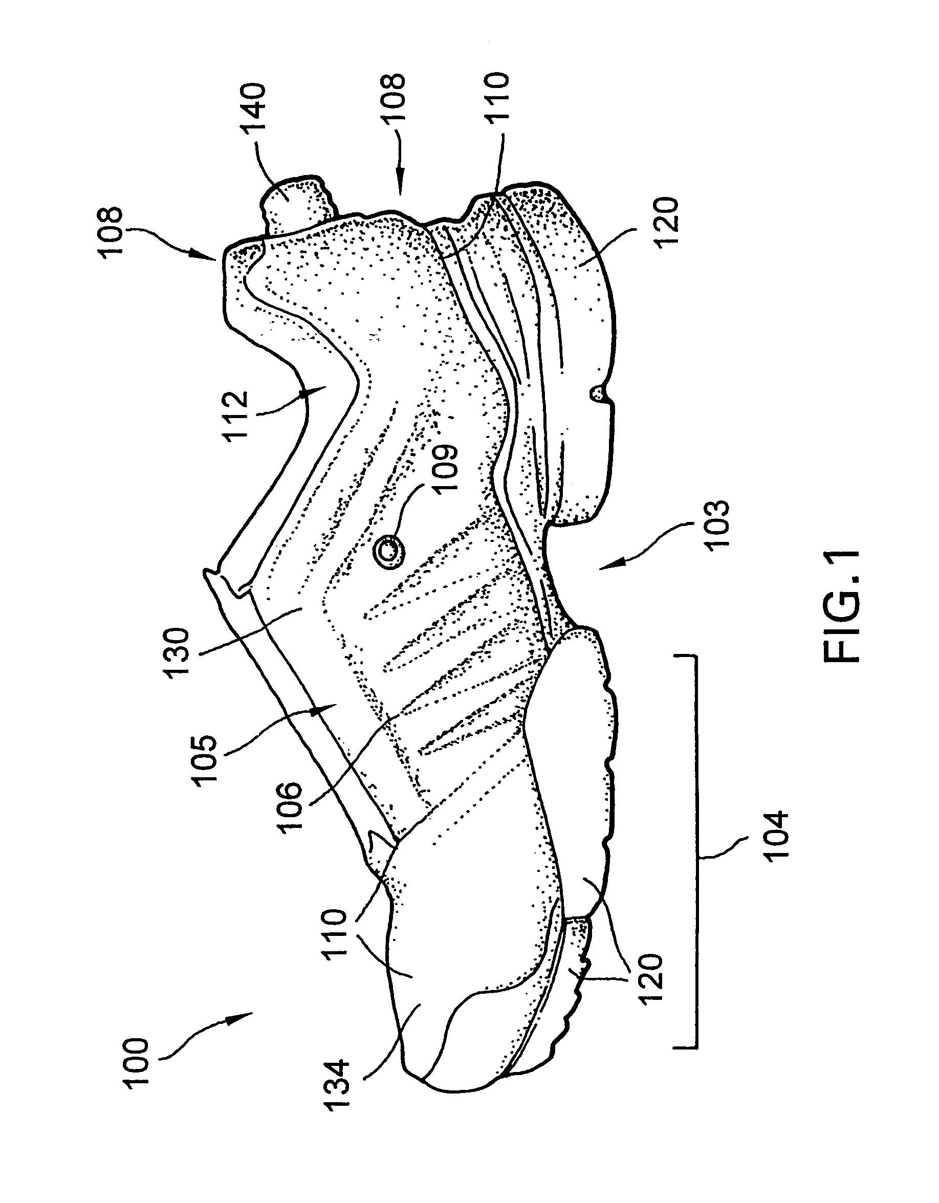
[0036]A shoe for a right foot according to the present invention is shown generally at 100 in FIG. 1. A corresponding shoe for the left foot could be a mirror image of shoe 100 and therefore, is not shown or described herein. As s...


PUM


Abstract

An article of footwear including a sole and an upper with an exterior and interior surface, and a bladder which comprises at least one of the exterior or interior surfaces. The bladder comprising sheets of polyurethane attached together via welding. The bladder includes a medial compartment and a lateral compartment attached to each other under the foot of the wearer. The article of footwear also includes a inflation mechanism for selectively introducing air to the chambers. The inflation mechanism is located under the foot of the wearer to be activated by the normal action of the wearer.

Description

[0001]This application is continuation of Ser. No. 10 / 851,088 filed May 24, 2004, which is a continuation of Ser. No. 10 / 186,717 filed on Jul. 2, 2002, now U.S. Pat. No. 6,785,985.BACKGROUND OF THE INVENTION[0002]1. Field of the Invention[0003]This invention relates to footwear, and more particularly to an athletic shoe having an inflatable bladder.[0004]2. Background Art[0005]Athletic footwear must provide stable and comfortable support for the body while subject to various types of stress. It is important that the shoe be comfortable and provide support during various foot movements associated with athletic activity.[0006]Articles of footwear typically include an upper and a sole, and are sold in a variety of sizes according to the length and width of the foot. However, even feet of similar length do not have the same geometry. Therefore, a conventional upper must be adjustable to provide support to various foot contours. Many different products and designs have focused on the nee...

Claims


Application Information

Patent Timeline
Patent Type & Authority Patents(United States)
IPC IPC(8): A43B13/20A43B23/00A43B5/00A43B7/32A43B7/14A43B23/02A43B23/07A43C11/00F16K15/20
CPCA43B13/20A43B13/203F16K15/202A43C11/00A43B23/07A43B23/029Y10T137/87394Y10T137/789A43B5/00A43B7/06A43B7/084A43B7/085A43B13/186A43B13/206
Inventor MARVIN, WILLIAMDAVIS, PAUL M.SWALES, GEOFFLITCHFIELD, PAUL E.
Owner REEBOK
Why Eureka
Try Eureka