Hydraulic active boom suspension for a telehandler

a boom suspension and telehandler technology, applied in the direction of fluid couplings, servomotors, couplings, etc., can solve the problems of high cost of vibration-damping systems, high cost of systems, and occupied space, and achieve the effect of cost-favorable construction

Inactive Publication Date: 2006-01-24
DEERE & CO
View PDF19 Cites 33 Cited by
  • Summary
  • Abstract
  • Description
  • Claims
  • Application Information

AI Technical Summary

Benefits of technology

[0014]In another preferred embodiment of the invention, the connecting line, advantageously in double-acting hydraulic cylinders, contains a non-return valve that closes the connecting line in the direction of the non-return valve that closes the chamber on the discharge side. The non-return valve can be required when, e.g., no check valve is contained in the connecting line. Since individual pressure-limiting units, for example chokes or diaphragms can be passed through in both directions and other pressure-limiting units can be sealed without leaks in only one direction, this can be assured by a non-return valve, so that no oil supply can take place into the connecting line from the chamber on the suction side to the chamber on the discharge side.
[0018]In another preferred embodiment of the invention, a load-holding valve is arranged in the line on the discharge side. The load-holding valve provides a safety function and assures a controllable lowering of the boom in case of an emergency, e.g. a pipe break in the line on the discharge side.
[0021]If a control valve is activated by the operator with an active suspension and a change in the position of the hydraulic piston is thereby effected, this is also signaled to the control unit. The new position of the hydraulic piston is then applied as a measurement quantity for the new target value to generate the control signal. In this way, it is assured that even with an activated suspension, it is possible to move the hydraulic piston in and out or that a signal is sent to the control unit when the control valve is activated in case of an activated suspension, by means of which signal a movement of the boom can be taken into account, so that a “new” target value is established when a desired movement of the boom takes place with activated suspension.
[0023]In another advantageous embodiment of the invention, the hydraulic cylinder contains means for measuring load, in particular a pressure sensor. A load measurement, for example through a pressure sensor arranged at the hydraulic piston, makes it possible to use an adjustable choke instead of the adjustable pressure-limiting valve in a needs-controlled suspension. The load measurement may be required in order that no hydraulic oil can leak through the first and second check valve and only when a preset limit pressure is reached are the first and second check valves opened in one of the two chambers. A limit pressure of this kind is reached when, for example, an impact affects the boom and the hydraulic piston should spring in our out. The load-measuring device sends a limit-pressure signal to the control unit, whereupon the check valve is opened. In consequence of this, the hydraulic piston is lowered or raised in the direction of the impact, whereupon the control unit generates a control signal, the adjustable choke is controlled, and the control valve opens, so that hydraulic oil can flow and the hydraulic piston resumes its original position. When the original position is reached, the check valve and the control valve are closed.
[0025]In addition, it turns out to be advantageous that a hydraulic suspension of this kind to be used in connection with hydraulic cylinders that are made with so-called load-holding valves, without the function of the load-holding valve being disabled. In this way, existing safety standards can be maintained.
[0027]Since fewer parts or components are required than with passive suspension system, a hydraulic system according to the invention can be constructed cost-favorably and from traditional components, without having to rely on developing special valves.

Problems solved by technology

They have the disadvantage that they are based, as a rule, on a constant suspension characteristic and thus their suspension characteristics do not react in a variable manner to the load acting on the stroke cylinder or the boom.
This system is expensive and takes up space.
This vibration-damping system is very expensive, since each hydraulic cylinder must be provided with two pressure sensors and each folding link with an angle of rotation sensor.
In addition, a very complex control algorithm is used, which is unsuitable for the active suspension of a boom of a loading vehicle.
It has the disadvantage that the recommended hydraulic circuit is set only to a pressure limit that can be set in advance and thus is not suitable in form for an active suspension system.

Method used


Image

  • Hydraulic active boom suspension for a telehandler
  • Hydraulic active boom suspension for a telehandler
  • Hydraulic active boom suspension for a telehandler

Examples


Embodiment Construction

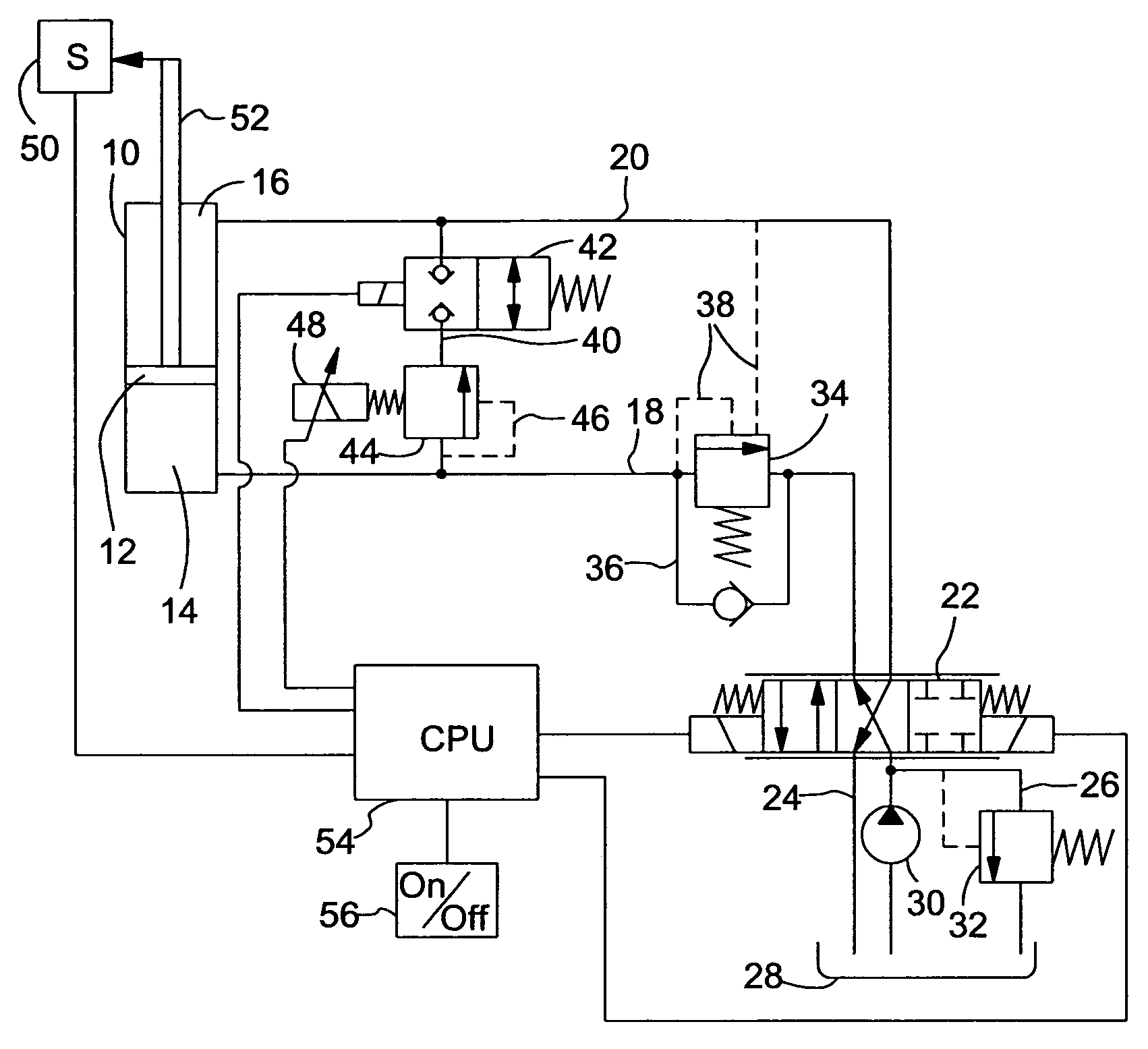
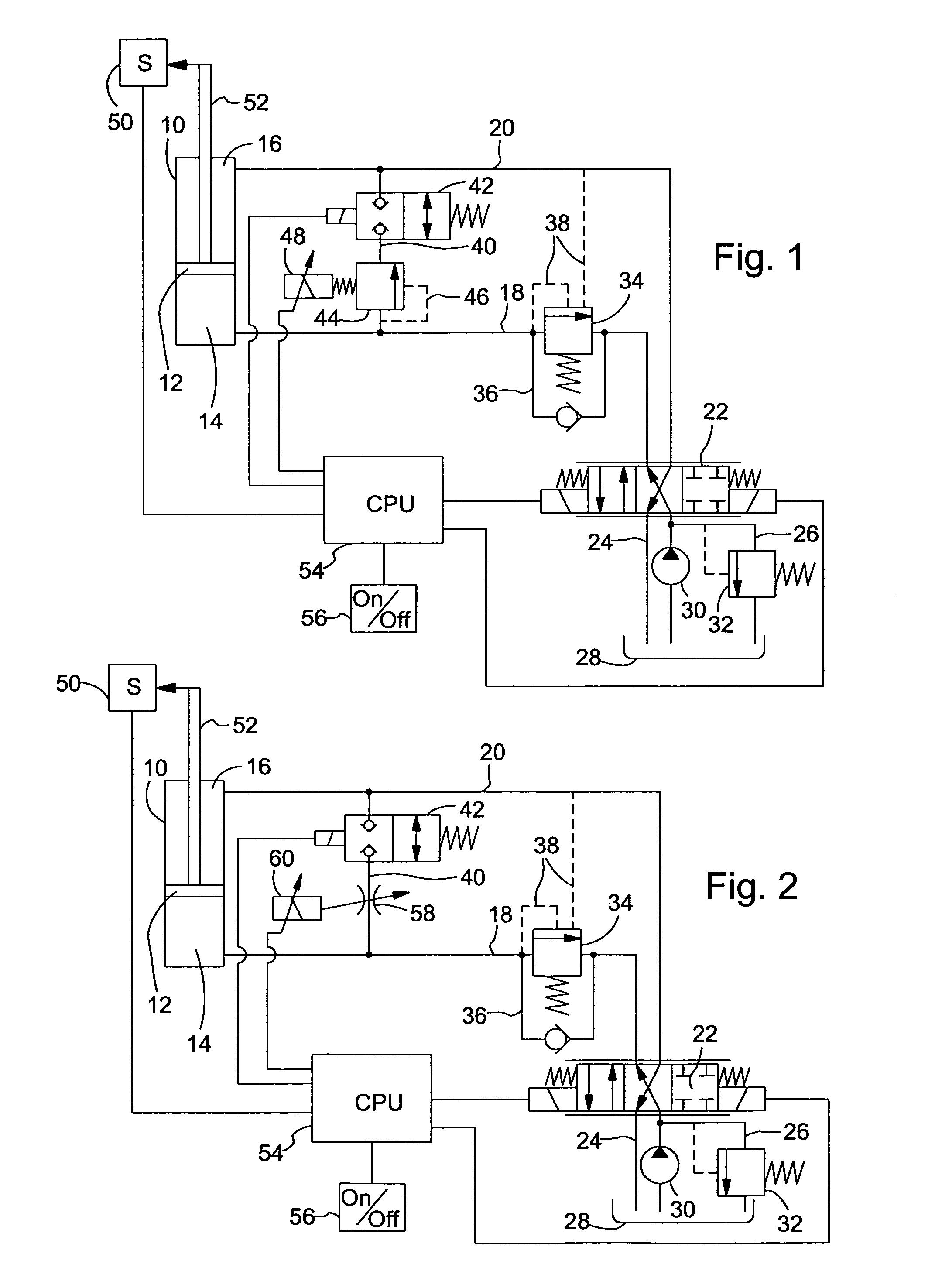
[0039]FIG. 1 shows a hydraulic cylinder 10 with a hydraulic piston 12, which serves to raise and lower the boom of a loading vehicle (both not shown). The head-end of the hydraulic cylinder 10 has a chamber 14, and the rod-end of the cylinder 10 has a chamber 16, with supply / return lines 18 and 20 respectively coupling the chambers 14 and 16 to a solenoid-operated, direction control valve 22. Control valve 22 is connected through an outflow line 24 and through a pressure-limiting line 26 to a hydraulic-oil tank 28. A hydraulic oil pump 30 supplies hydraulic oil through the control valve 22 to each hydraulic line 18, 20.

[0040]Control valve 22 can be switched among three positions, namely, a closed position, in which no flow takes place through the hydraulic lines 18 and 20, a stroke position, in which hydraulic line 18 is supplied with hydraulic oil and hydraulic line 20 is coupled to the hydraulic tank 28, and a drop position, in which hydraulic line 20 is supplied with hydraulic oi...


PUM


Abstract

A suspension for the boom of a loading vehicle includes a hydraulic cylinder for raising and lowering, or for extending and retracting (in the case of a telescopic cylinder), a boom. A direction control valve is provided for selectively routing hydraulic oil to and from at least a head-end chamber of the cylinder. A position sensor senses the position of the hydraulic piston rod, at the start of operation, and sends a sends a target signal representing this beginning position to a control unit which determines the difference between the target signal and a signal representing a current position of the piston rod. When this difference equals a preset difference threshold, a pressure-limiting unit, in the form of a valve or choke, is activated so as to control fluid flow to and from the head-end chamber so as to return the piston rod to its initial position which generated the target signal. Different embodiments have different valve component arrangements for influencing the reaction time of the suspension and / or for adapting the circuitry for use with single-acting, double-acting or telescopic boom cylinders.

Description

FIELD OF THE INVENTION[0001]A hydraulic suspension, especially for a boom of a loading vehicle, with at least one hydraulic cylinder, which has at least one chamber, a control valve that is connected by at least one hydraulic line to the chamber(s) and that optionally produces a connection to a hydraulic oil pump and a hydraulic-oil tank, and a connecting line.BACKGROUND OF THE INVENTION[0002]According to the present state of the art, tractors with front loaders, such as wheel loaders, telescope loaders, crane vehicles, and similar land vehicles are provided with suspension / shock-absorbing systems that consist of one or more gas-filled hydraulic-storage units, which are connected as needed to a hydraulic stroke cylinder of one of the booms, in order to reduce the effects of vibrations of the boom on the chassis of the vehicle and vice versa. In this connection, we speak of “passive” suspension systems. They have the disadvantage that they are based, as a rule, on a constant suspensi...

Claims


Application Information

Patent Timeline
Patent Type & Authority Patents(United States)
IPC IPC(8): F16D31/02B66F9/065B66F9/22E02F9/22F15B11/028F15B13/02F15B21/04
CPCB66F9/065E02F9/2207F15B11/028F15B13/021F15B21/008B66F9/22F15B2211/765F15B2211/30525F15B2211/3058F15B2211/3116F15B2211/3144F15B2211/327F15B2211/40515F15B2211/41536F15B2211/41581F15B2211/426F15B2211/45F15B2211/473F15B2211/50518F15B2211/50545F15B2211/5151F15B2211/526F15B2211/528F15B2211/55F15B2211/6313F15B2211/6336F15B2211/6346F15B2211/7052F15B2211/7053
Inventor BITTER, MARCUS
Owner DEERE & CO
Why Eureka
Try Eureka