Hydroaccumulator, in a particular a bladder accumulator

a technology of accumulator and bladder, which is applied in the direction of valve operating means/releasing devices, containers, transportation and packaging, etc., can solve the problems of high production cost, large space occupied by the known valve body in the direction of displacement in the connecting sleeve, and complex and costly machining process in production, etc., to achieve low production cost, simple structure, and economic implementation

Inactive Publication Date: 2006-01-24
HYDAC TECH GMBH
View PDF17 Cites 6 Cited by
  • Summary
  • Abstract
  • Description
  • Claims
  • Application Information

AI Technical Summary

Benefits of technology

[0005]Objects of the present invention are to provide a hydraulic accumulator where the valve body occupies little space, is geometrically simple in structure, can be economically implemented, and allows optimized flow behavior in the area of the flow into the fluid space.
[0007]By integrating the fluid channels into the interior of the valve body, complex machining for differentiated shaping of the outside surface of the valve body, as in the known approaches, is unnecessary. Moreover, by means of the respective fluid channels, a homogeneous outflow behavior of the fluid into the fluid space is ensured. Especially when a bladder accumulator is implemented, flow then takes place carefully around the separating membrane which is sensitive to pressure peaks and which ordinarily is formed of a rubber-elastic material. This arrangement leads to an increased service life for the hydraulic accumulator of the present invention.
[0008]Production is especially simple if the valve arrangement is a sliding valve, with the connecting sleeve being used as the valve housing and with its circular cylindrical inside surface defining the piston bore for the valve body which is made as a sliding piston.

Problems solved by technology

The disadvantage is the resulting high production costs due to the required cost for producing and machining of a host of individual parts as a result of this known valve design.
Thus, the known valve body occupies considerable space in its direction of displacement in the connecting sleeve.
In conjunction with the different diameters, grooves and recesses, beveled surfaces and the transverse hole on the other end of the valve body, a resulting complex geometry requires a complex and costly machining process in production.
As a result of the repeated deflection of the fluid flow, especially in the area of the incident flow of the medium into the fluid space, unfavorable flow behavior is implemented so that the known approach to hydraulic accumulators with sensitive membrane bladders is not suitable.
Due to the fluid-carrying transverse holes, the flow behavior cannot be choked and is consequently unfavorable in the area of inflow of the medium into the fluid space.

Method used


Image

  • Hydroaccumulator, in a particular a bladder accumulator
  • Hydroaccumulator, in a particular a bladder accumulator
  • Hydroaccumulator, in a particular a bladder accumulator

Examples


Embodiment Construction

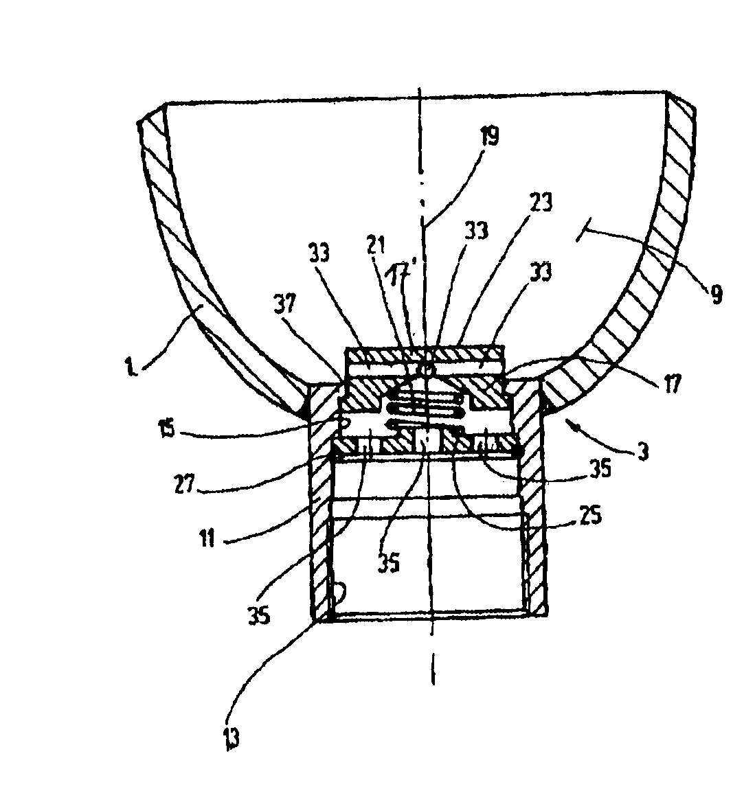
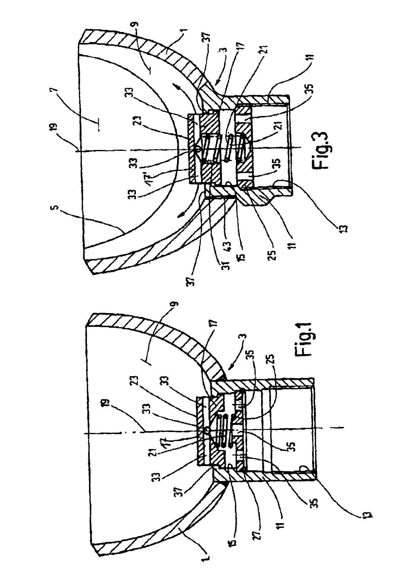
[0016]In FIG. 1, only the section of the pressure tank adjacent to the fluid-side access 3 is shown. The opposite end area (not shown) of the pressure tank 1 has a conventionally configured gas-side access to the interior space of a storage bladder 5 (only schematically illustrated in FIG. 3). Storage bladder 5 forms the movable separating element separating the gas space 7 from the fluid space 9 in the interior of the pressure tank.

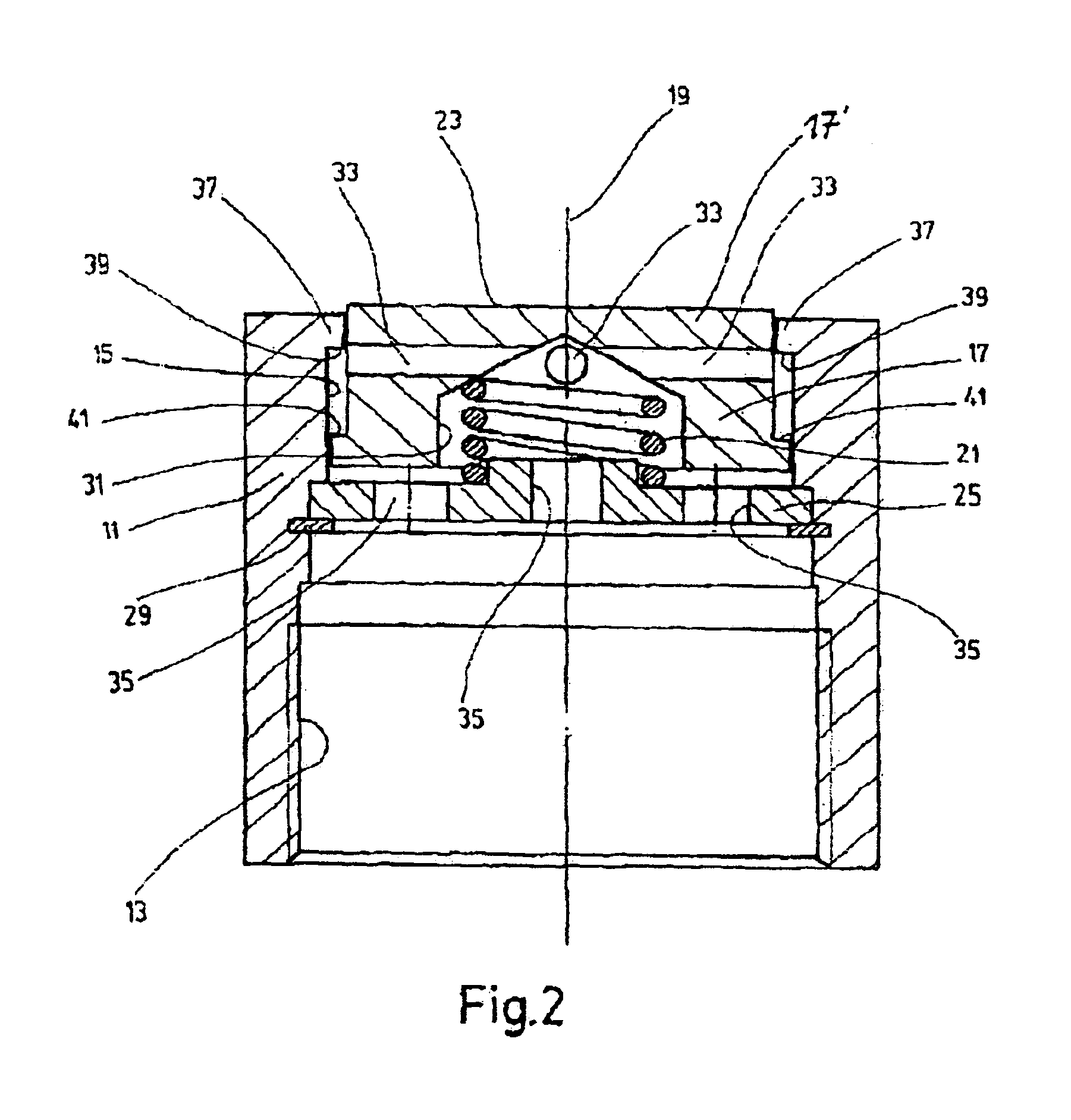
[0017]In the embodiment shown in FIG. 1, the fluid-side access 3 comprises a fluid connecting sleeve 11 welded onto the end wall of the pressure tank 1 adjacent to the fluid space 9. The connecting sleeve 11 is a circularly cylindrical sleeve and has an inside thread 13 on its outer free end for the connection of a fluid line (not shown). In the end area adjacent to the fluid space 9, the connecting sleeve 11 forms a piston bore 15 in which a sliding piston 17 is movably guided. The connecting sleeve 11 thus forms the valve housing for a sliding valve wi...


PUM


Abstract

A hydroaccumulator, in particular a bladder accumulator, includes a pressurized container (1) and a separation element (5) located in the container to separate a gas chamber (7) lying adjacent to an inlet on the gas side from a fluid chamber (9) lying adjacent to an inlet on the fluid side inlet (3), having a fluid connecting sleeve (11) and a valve arrangement located in the connecting sleeve (11). The valve body (17) has a transversal bore (33). The valve body is pretensioned in an open position which allows the passage of fluid and can be displaced into a closed position by a displacement of the separation element (5). The interior surface (15) of the connecting sleeve (11) lies directly against the valve body (17) and guides the displacement of the body between the open and closed positions. The side of the valve body (17′) that faces the separation element (5) is configured as a planar plate extending partially into the fluid chamber (9). The diameter of the valve body (17) is greater than its height, measured in the direction of displacement of the valve body (17). The valve arrangement has a plate-valve construction of small proportions and can be cost-effectively produced.

Description

FIELD OF THE INVENTION[0001]The present invention relates to a hydroaccumulator, in particular a bladder accumulator, with a pressure tank and a separating element located in and separating a gas space from a fluid space in the pressure tank. The gas space borders a gas-side access. The fluid space borders a fluid-side access having a fluid connecting sleeve and a valve arrangement located in the connecting sleeve. The valve includes a valve body having at least one transverse hole and is normally pretensioned into its open position to clear the fluid passage, and can be moved into its closed position by the displacement of the separating element. The inside surface of the connecting sleeve for the valve body directly adjoining the valve body forms the guide for its displacement between the open position and the closed position.BACKGROUND OF THE INVENTION[0002]Hydraulic accumulators with valves operated by the separating element are commercially available. In the technical reference...

Claims


Application Information

Patent Timeline
Patent Type & Authority Patents(United States)
IPC IPC(8): F16L55/04F15B1/08F15B1/16F15B1/22
CPCF15B1/165F15B1/22F15B2201/43F15B2201/3152F15B2201/411F15B2201/205Y10T137/7792
Inventor WEBER, NORBERT
Owner HYDAC TECH GMBH
Why Eureka
Try Eureka