Vascular suction cannula, dilator and surgical stapler

Inactive Publication Date: 2006-01-24
MEDTRONIC ANGIOLINK
View PDF60 Cites 251 Cited by
  • Summary
  • Abstract
  • Description
  • Claims
  • Application Information

AI Technical Summary

Benefits of technology

[0009]Thus, the present invention solves the aforementioned drawbacks by providing a suction cannula, dilator, stapler and staple that are simple to use and manufacture. In one aspect, the present invention provides a suction cannula that is concentrically aligned with a puncture site (e.g., puncture in an artery or vein) and provides vacuum about the periphery of the

Problems solved by technology

While this device is useful when stapling a graft vein or the like, unfortunately, this device would be inappropriate when the entirety of the tubular tissue is not accessible, such as following percutaneous catheterization procedures.
Thus, this device would not be useful in these circumstances.
Similar to the previous disclosures, this device is useful for the attachment of one tubular tissue onto another, however, is inadequate in sealing a puncture in an artery, vein o

Method used


Image

  • Vascular suction cannula, dilator and surgical stapler
  • Vascular suction cannula, dilator and surgical stapler
  • Vascular suction cannula, dilator and surgical stapler

Examples


Example

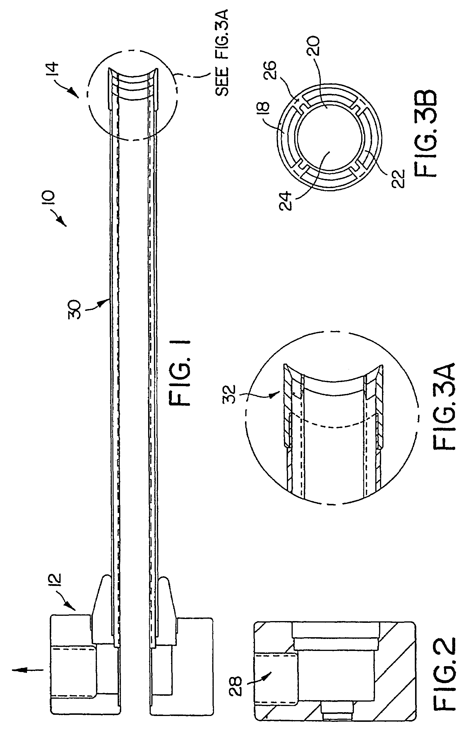
[0035]FIGS. 1–3B depict various views of one embodiment of the suction cannula 10 of the present invention. Essentially, cannula 10 comprises a tubular member 30, a proximal end 12 and a distal end 14. The distal end 14 is adapted to permit vacuum affixation of the cannula 10 to a vascular wall, or other tissue as will be described below. As shown in FIG. 3B, the tubular member 30 is preferably constructed with a tube 20 within a tube 18. As will be described below, the chamber 22 between the tubes 18 and 20 is used as a vacuum chamber. Passage 24 permits a dilator and / or stapler device (each discussed below) and / or other surgical devices to pass therethrough. Support members 26 are provided to concentrically affix tubes 18 and 20. The proximal end 12, as shown in FIG. 2 includes a vacuum port 28 that can be attached to an external vacuum (not shown). Vacuum port 28 communicates with chamber 22 (between inner tube 20 and outer tube 18) to provide a vacuum therein. As shown in FIG. 3...


PUM

PropertyMeasurementUnit
Shapeaaaaaaaaaa
Dimensionaaaaaaaaaa

Abstract

A suction cannula, dilator, stapler and staple are provided herein. The suction cannula is concentrically aligned with a puncture site (e.g., puncture in an artery or vein) and provides vacuum about the periphery of the puncture site so that the puncture hole is always located during a medical procedure, and to thereby permit a surgeon to quickly and efficiently close the puncture using, for example, a stapling device. In the preferred embodiment the suction cannula has a tube-in-tube construction having an inner tube and an outer tube where a vacuum can be applied between the tubes. The dilator (and suction cannula) centers around a guide wire (that is already in place within the venous structure) and follows the path of the guide wire to the puncture site. Preferably, the dilator has a tapered tip on the distal end that enters a hole made in the vein or artery. A blood indicator is provided on the proximal end to provide visual feedback when the surgeon is in the artery (i.e., pulsating blood indicates that the tip of the dilator is in the artery). Also preferably, the dilator includes a tapered tip on the distal end that is radially collapsible so that the dilator can be withdrawn from the artery and the suction cannula is thereby permitted to advance over the dilator to the artery wall. The stapler is provided which holds a multi-pronged staple on a shaft at the distal end. The stapler is constructed to slide into the suction cannula (i.e., the inner tube of the cannula) to approach the puncture in the artery, to permit the stapling of the artery. Preferably, the distal end of the stapler includes a T-flange that holds a staple and a crimping mechanism that crimps the staple into the artery, thereby sealing the puncture. The T-flange permits the staple to be held and inserted into the artery wall. An oval hub on the T-flange is provided that mates with an oval hole in the center of the staple. To hold a staple, a staple is placed on the hub and rotated 90 degrees, thereby affixing the staple to the stapler. Once the staple is crimped onto the artery wall, the shaft can be rotated 90 degrees, thereby aligning the oval hub and the oval hole, so that the stapler can be removed. Preferably, the staple includes a plurality of prongs that are inserted into the vascular wall.

Description

[0001]This application is a continuation application under 37 CFR §1.53(b) of application Ser. No. 09 / 486,185 filed Feb. 18, 2000 now abandoned, which claims priority to U.S. Provisional application No. 60 / 093,701 filed Jul. 22, 1998, and PCT application No. PCT / US99 / 16476 filed Jul. 21, 1999, all of which are hereby incorporated by reference in their entirety.BACKGROUND OF THE INVENTION[0002]1. Field of the Invention[0003]The present invention relates to a vascular suction device, a dilator and a stapler for the closure of a puncture made in the wall of an artery or vein during a medical procedure. The present invention has particular utility for use in and around the femoral artery during and after coronary / cardiac procedures. Other utilities include soft-tissue anchoring, meniscal repair, thoracic lung closure, endoscopic procedures, esophageal repair, laparoscopy, skin / epidermal wound closure and general tissue closure.[0004]2. Description of Related Art[0005]Surgical stapling i...

Claims


Application Information

Patent Timeline
IPC IPC(8): A61B17/10A61B17/00A61B17/02A61B17/064A61B17/068A61B17/115A61B17/30A61B17/34
CPCA61B17/0057A61B17/0684A61B17/3439A61B17/3421A61B17/0218A61B17/3417A61B2017/3488A61B2017/00637A61B2017/00668A61B2017/306
Inventor TALLARIDA, STEVEN J.ETTLINGER, MARK
Owner MEDTRONIC ANGIOLINK
Why Eureka
Try Eureka