Eureka AIR delivers breakthrough ideas for toughest innovation challenges, trusted by R&D personnel around the world.

Pulse interval to voltage converter and conversion method thereof

Active Publication Date: 2006-01-24
KUO TERRY B J +2
View PDF7 Cites 12 Cited by
  • Summary
  • Abstract
  • Description
  • Claims
  • Application Information

AI Technical Summary

Benefits of technology

[0008]The objective of the present invention is to provide a programmable PIVC and conversion method thereof, through which a delay is set in advance, the count of the clock between two pulses is calculated and the resolution of the output voltage is regulated, with a view to performing regulation to meet various needs. In addition, the PIVC and conversion method thereof of the present invention ignore pulse signals during a delay so as to avoid the influence of short-period noise.
[0011]Additionally, the PIVC may further comprise a frequency regulator and an underflow protection unit. The frequency regulator can either be a frequency divider or a frequency multiplier for regulating the resolution of the output voltage. The underflow protection unit turns back external signals while the delay unit is operating, so as to minimize interference from noise.

Problems solved by technology

Nevertheless, the aforesaid design has the following problems.
First, low resolution of output voltage may occur.
Hence, it does not make good use of the bits available, resulting in the low-resolution display of voltage.
However, adding more bits will greatly increase the cost.
Secondly, the PIVC may be susceptible to interference.
Since the conventional method has the aforementioned problems of low resolution and being susceptible to interference, it is necessary to improve the design.

Method used


Image

  • Pulse interval to voltage converter and conversion method thereof
  • Pulse interval to voltage converter and conversion method thereof
  • Pulse interval to voltage converter and conversion method thereof

Examples


Embodiment Construction

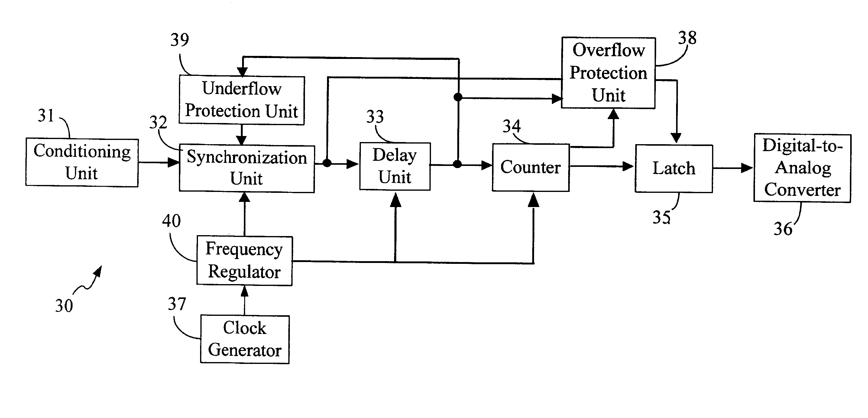
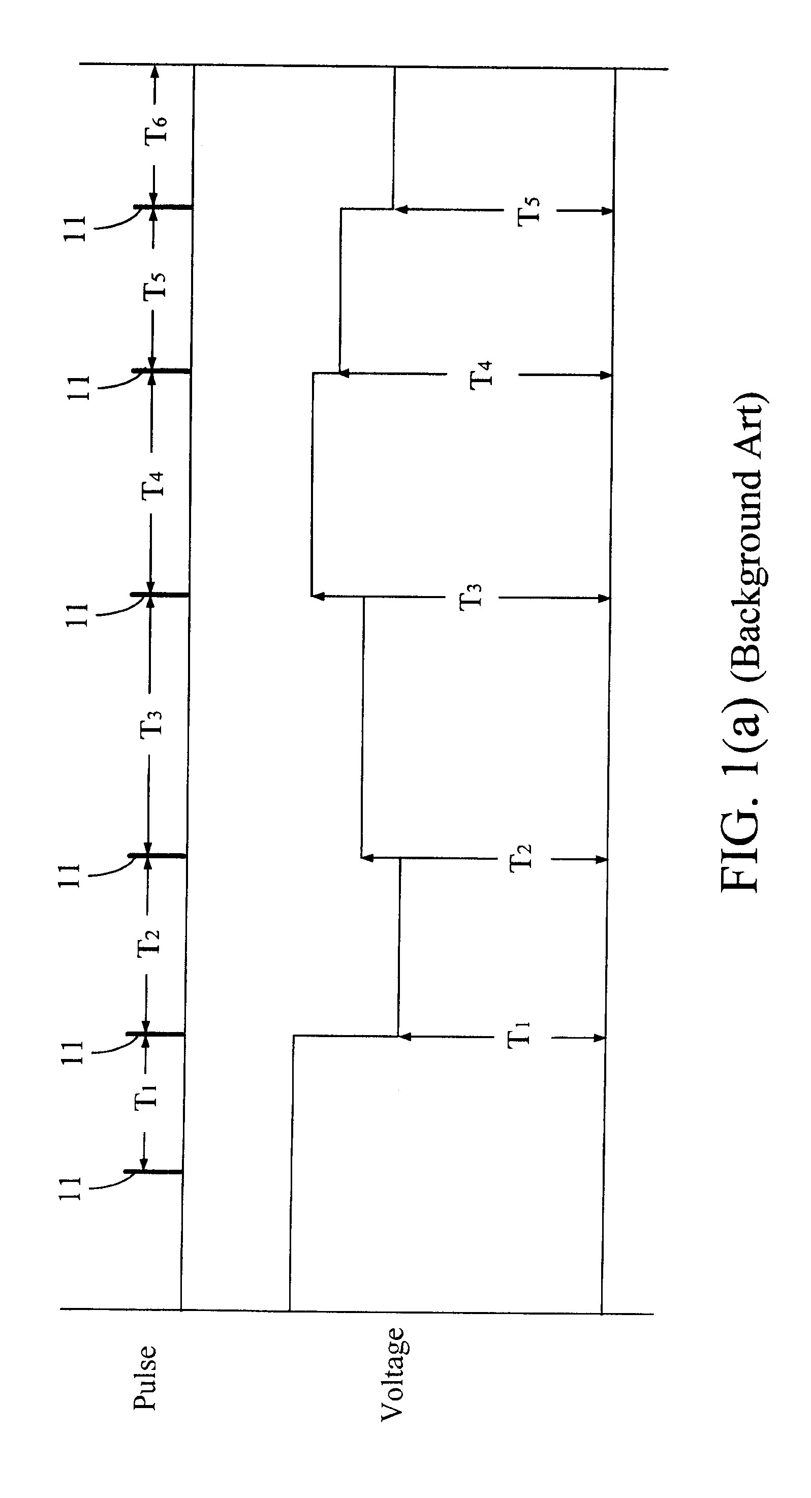
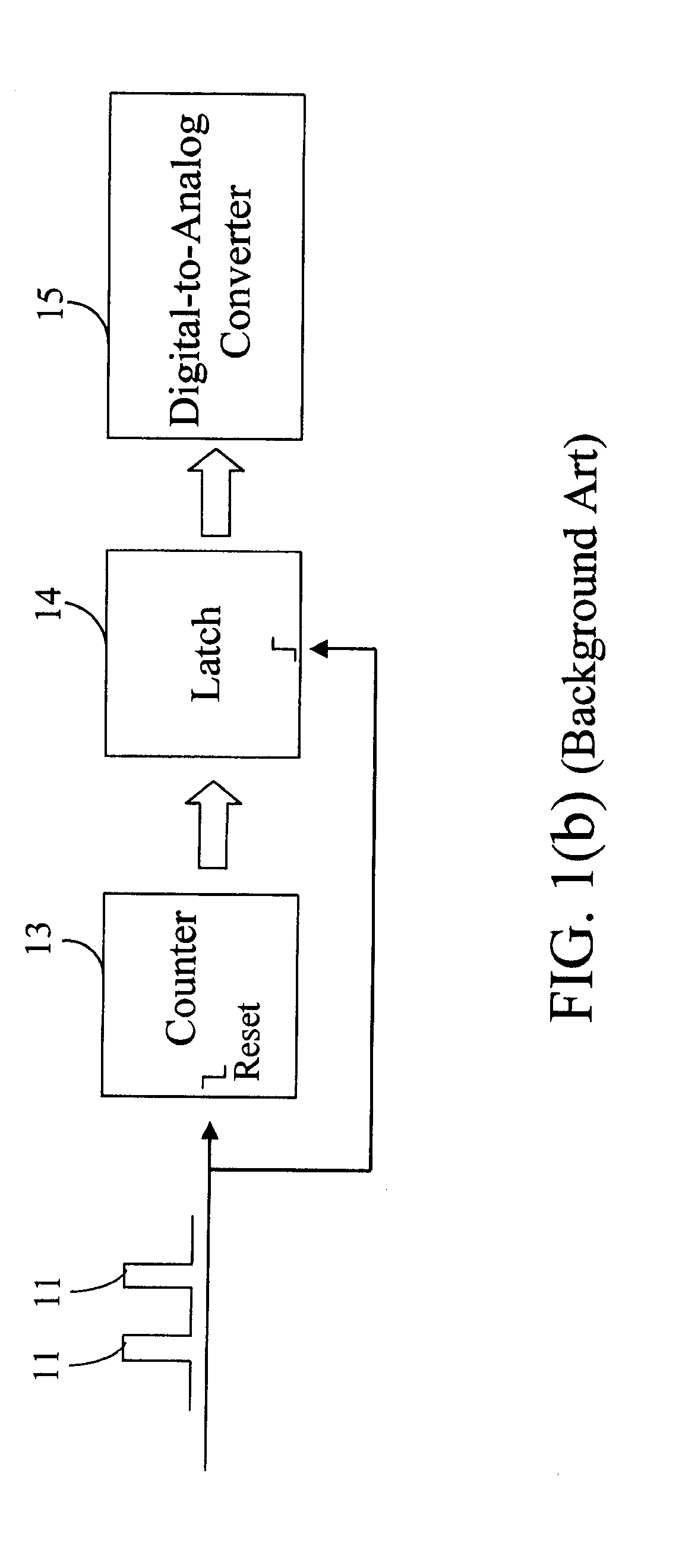
[0020]A PIVC 20 shown in FIG. 2(a) is exemplified to highlight the technical characteristics and the advantages of the present invention. The PIVC 20 comprises a counter 21, a latch 22, a digital-to-analog converter 23, a delay unit 24, a frequency regulator 25, an underflow protection unit 26 and a clock generator 27. Pulses 28 are input to the delay unit 24 and eventually converted to analog signals of output voltage by the digital-to-analog converter 23. New components, namely the delay unit 24, the frequency regulator 25 and the underflow protection unit 26, are incorporated into the PIVC 20, compared to the conventional art. The delay unit 24 is intended for the programming of the default duration of delay, so as to delay the time for the counter 21 to reset to zero. If it is set beforehand, that the zero-resetting operation of the counter is to be delayed for Y clock cycles, and that after the delay the pulse intervals between a clock 28 and the next clock 28 are T1 to T6, res...


PUM


Abstract

A Pulse Interval to Voltage Converter (PIVC) and conversion method thereof is revealed. The PIVC comprises a clock generator, a counter, a latch, a digital-to-analog converter (DAC), a delay unit, a frequency regulator and an underflow protection unit. New components, such as the delay unit, the frequency regulator and the underflow protection unit, are incorporated into the present invention, unlike the conventional art. The delay unit is intended for the programming of the default duration of delay, so as to delay the time for the counter to reset to zero, and in consequence regulate the baseline of the output voltage. The frequency regulator can regulate the clock generation frequency of the clock generator, so as to regulate the resolution of the output voltage. The underflow protection unit turns back external signals while the delay unit is operating, so as to minimize interference from noise.

Description

BACKGROUND OF THE INVENTION[0001]1. Field of the Invention[0002]The present invention is related to a Pulse Interval to Voltage Converter (PIVC) and the conversion method thereof, more particularly, to a programmable PIVC and conversion method thereof.[0003]2. Description of the Related Art[0004]PIVCs are equipment commonly used in industry and biomedicine, which can express every pulse interval in the form of voltage. As shown in FIG. 1(a), T1 and T6 denote the intervals of each pulse 11, and after conversion, its voltage is directly proportional to the interval of each pulse 11. In other words, the greater an interval is, the greater the output voltage is. In addition, PIVCs are roughly divided into two types, namely analog and digital, depending on the design.[0005]FIG. 1(b) illustrates the operation of a digital PIVC, that is, a counter 13 starts to run immediately after a pulse 11 is received, but on receipt of the next pulse 11, the counter 13 resets to zero and then runs agai...

Claims


Application Information

Patent Timeline
IPC IPC(8): H03D3/00H03K9/08
CPCH03K9/08
Inventor KUO, TERRY B. J.YANG, CHERYL C. H.
Owner KUO TERRY B J
Why Eureka
Eureka Blog
Learn More