Supercharge Your Innovation With Domain-Expert AI Agents!

Phase and frequency lock detector

Inactive Publication Date: 2006-01-24
IBM CORP
View PDF4 Cites 10 Cited by
  • Summary
  • Abstract
  • Description
  • Claims
  • Application Information

AI Technical Summary

Problems solved by technology

Conventionally, PLL lock detectors are implemented with two or more large frequency counters, and thus may take up valuable space in a circuit area.
Moreover, since both the counters are continuously toggling during steady-state locked conditions, the prior-art PLL lock detectors can dissipate significant power.
These large frequency counters may also introduce digital switching noise, which can seriously limit the performance of the sensitive analog components of a mixed-signal PLL design.
Other prior-art PLL lock detectors use delay lines, which will limit the frequency range for lock detection and are difficult to manufacture with the appropriate tolerances.
Also, some other prior-art PLL lock detectors require low-pass filter components, which may take up significant space in a circuit area and require strict manufacturing process controls.

Method used


Image

  • Phase and frequency lock detector
  • Phase and frequency lock detector
  • Phase and frequency lock detector

Examples


Embodiment Construction

[0018]In the following discussion, numerous specific details are set forth to provide a thorough understanding of the present invention. However, it will be obvious to those skilled in the art that the present invention may be practiced without such specific details. In other instances, well-known elements have been illustrated in schematic or block diagram form in order not to obscure the present invention in unnecessary detail.

[0019]It is further noted that, unless indicated otherwise, all functions described herein may be performed in either hardware or software, or some combination thereof. In a preferred embodiment, however, the functions are performed by a processor such as a computer or an electronic data processor in accordance with code such as computer program code, software, and / or integrated circuits that are coded to perform such functions, unless indicated otherwise.

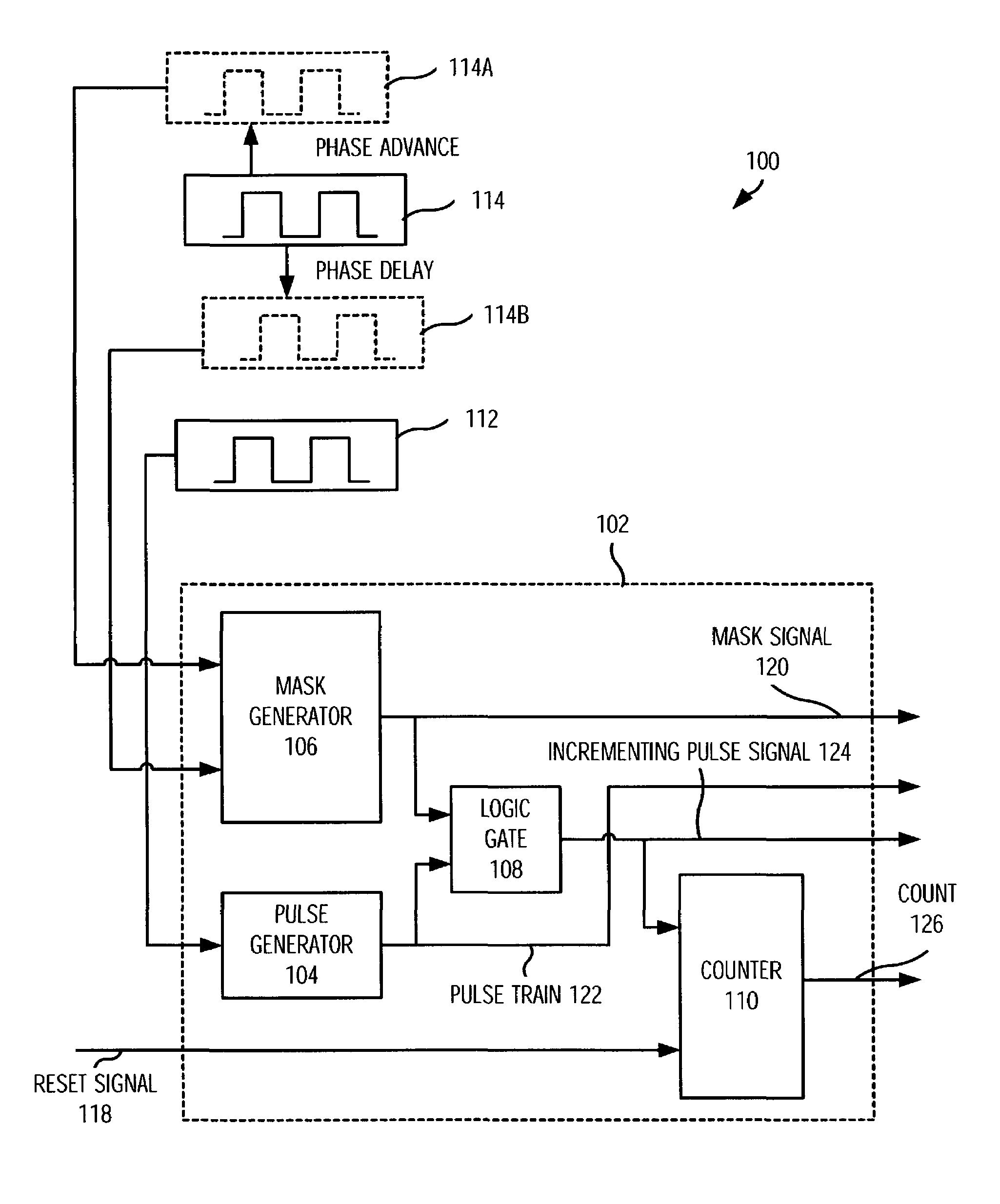
[0020]In FIG. 1, a reference numeral 100 designates a block diagram illustrating a lock detector 102 in ...


PUM


Abstract

A lock detector and method is provided for detecting lock between first and second signals. The lock detector includes a pulse generator for receiving the first signal and generating a pulse train from the first signal. Each pulse corresponds to at least one of rising and falling edges of the first signal in each period of the first signal. The lock detector also includes a mask generator for generating a mask signal from the second signal such that the mask signal has a mask state around at least one of rising and falling edges of the second signal in each period of the second signal. Additionally, the lock detector has a logic gate, which receives the pulse train and the mask signal from the pulse generator and the mask generator, respectively. The logic gate generates an incrementing pulse signal by combining the pulse train with the mask signal.

Description

BACKGROUND OF THE INVENTION[0001]1. Field of the Invention[0002]The invention relates generally to a lock detector and, more particularly, to a lock detector used in conjunction with phase-locked loop or similar oscillation circuits.[0003]2. Description of the Related Art[0004]A phase-locked loop (PLL) may require many thousands or millions of cycles before reaching its steady-state locked condition from its initial power-on state. An indication of the locked condition for the PLL is useful as a diagnostic tool or may be used as part of the power-on-reset sequencing for a system during initial power-up. Conventionally, PLL lock detectors are implemented with two or more large frequency counters, and thus may take up valuable space in a circuit area. Moreover, since both the counters are continuously toggling during steady-state locked conditions, the prior-art PLL lock detectors can dissipate significant power. These large frequency counters may also introduce digital switching nois...

Claims


Application Information

Patent Timeline
IPC IPC(8): H03D3/24H03L7/095
CPCH03L7/095Y10S331/02
Inventor BOERSTLER, DAVID WILLIAMWEITZEL, STEPHEN DOUGLAS
Owner IBM CORP
Features
  • R&D
  • Intellectual Property
  • Life Sciences
  • Materials
  • Tech Scout
  • Unparalleled Data Quality
  • Higher Quality Content
  • 60% Fewer Hallucinations
Learn More