Magnetic multilayer device, method for producing such a device, magnetic field sensor, magnetic memory and logic gate using such a device

a multi-layer device and multi-layer technology, applied in the field of magnetic materials, can solve the problems of low longitudinal resistivity of materials, increased difficulty in deliberately changing the magnetization direction, and very rapid decrease, and achieve high longitudinal resistivity, high extraordinary hall coefficient, and high perpendicular anisotropy

Active Publication Date: 2008-06-26
COMMISSARIAT A LENERGIE ATOMIQUE ET AUX ENERGIES ALTERNATIVES +1
View PDF0 Cites 70 Cited by
  • Summary
  • Abstract
  • Description
  • Claims
  • Application Information

AI Technical Summary

Benefits of technology

[0049]The present invention proposes a means of producing a magnetic multilayer device having an out-of-plane anisotropy field having a value close to its demagnetizing field, so that the device is extremely sensitive to a magnetic field which can be detected by measuring the extraordinary Hall effect, by measuring magnetoresistance or measuring the Kerr effect or the Faraday magneto-optical effect. The material used makes it possible to combine the advantages of the various materials stated above, namely high perpendicular anisotropy making it possible to compensate or even exceed the inherent shape anisotropy of thin films and, in the particular case where the Hall effect is measured, high longitudinal resistivity and a high extraordinary Hall coefficient.
[0053]High longitudinal resistivity is obtained by using thin magnetic layers that alternate with the oxide, hydride or nitride layers. They are therefore highly resistive due to the important role played by interfacial diffusions. Because all these layers are only repeated a small number of times (typically less than 20 repetitions) in order to obtain the final multilayer structure, the electrical resistance of the entire stack is therefore high.

Problems solved by technology

This also, however, makes it more difficult to deliberately modify the magnetization direction, such as, for instance, when the material is used as a magnetic memory in which information is in fact coded by the magnetization direction.
Unfortunately, these materials have low longitudinal resistivity due to the low resistivity of their metallic components.
Unfortunately, this sensitivity is obtained at low temperature (−100° C.) and diminishes very rapidly before reaching a value of virtually zero at ambient temperature and this restricts the field of application of these materials significantly (see O. Riss, A. Tsukernik, M. Karpovsky, A. Gerber, “Reorientation phase transition and sensitivity of the extraordinary Hall-effect-based sensors”, Journal of Magnetism and Magnetic Materials, 2006, Vol. 298, p.
Finally, the authors do not intend these materials for use in the area of magnetic field sensors or magnetic memories or logic components based, in particular, on measuring the extraordinary Hall effect.

Method used


Image

  • Magnetic multilayer device, method for producing such a device, magnetic field sensor, magnetic memory and logic gate using such a device
  • Magnetic multilayer device, method for producing such a device, magnetic field sensor, magnetic memory and logic gate using such a device
  • Magnetic multilayer device, method for producing such a device, magnetic field sensor, magnetic memory and logic gate using such a device

Examples


first embodiment

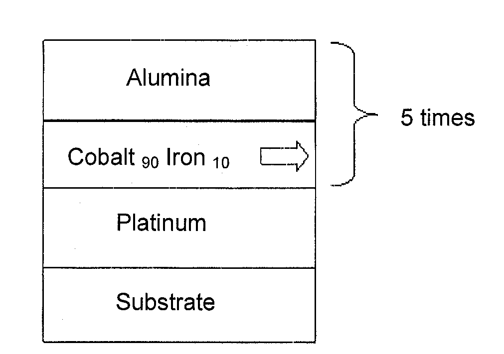
[0107]FIG. 4 is a schematic view of the invention. In this Figure (and subsequent FIGS. 6, 8, and 11), the direction of the arrows indicates the magnetization direction (in the absence of an applied magnetic field) of the magnetic layers (horizontal arrow for planar magnetization, vertical arrow for perpendicular magnetization).

[0108]Immediately after the substrate there is a layer of growth initiating material, such as platinum for example. It can be replaced by another material or by a combination of other materials regarded as suitable for initiating satisfactory growth of thin metallic layers, especially those that result in extremely slight surface roughness. Examples include titanium nitride, copper nitride, ruthenium, tantalum, iridium-manganese alloys, platinum-manganese, nickel-iron-chrome, etc. It is also possible not to use this initial layer if it is established that quality of growth of the magnetic layer on the substrate is satisfactory.

[0109]This is followed by the fi...

second embodiment

[0124]FIG. 6 is a schematic view of the invention. FIG. 7 shows variation in Hall resistance as a function of magnetic field for a structure of the Pt 1.0 nm / Co 0.6 nm / Al2O3 2.0 nm / (CoFe 0.6 nm / Al2O3 2.0 nm)5 type, i.e. a (Co / Al2O3) bilayer deposited on a platinum growth layer having a thickness of 1 nm and topped by five (CoFe / Al2O3) bilayers.

[0125]As in the previous case, the longitudinal resistivity of this stack is also of the order of 1000 μΩcm. The Hall resistance is smaller than in the previous case (of the order of 4Ω at saturation rather than 8Ω), firstly because of the larger number of stack repetitions (6 in total rather than 5) and secondly the negative effect of the thicker initial platinum layer (1.0 nm rather than 0.3 nm) which derives a fraction of the current that flows through the structure.

[0126]In contrast, this slightly thicker platinum layer significantly enhances perpendicular magnetic anisotropy properties. In fact, the perpendicular anisotropy field is only ...

third embodiment

[0129]This case is shown in the invention which is schematically illustrated in FIG. 8 with a stack identical to that shown in FIG. 6, but for which the oxidation conditions were slightly modified (oxygen pressure slightly reduced during plasma oxidation of aluminum layer), consequently stabilizing the magnetization direction of the layers perpendicular to the plane of said layers, even in the absence of an applied magnetic field. This type of structure is therefore ideally suitable for producing magnetic memories or magnetic logic gates.

[0130]As shown in FIG. 9, in this case one obtains two stable states in a zero magnetic field, i.e. a Hall resistance of + / −3.5Ω, depending whether magnetic fields are positive or negative. Hall resistance inversion occurs with extremely weak magnetic fields of the order of 0.3 mT in the present case.

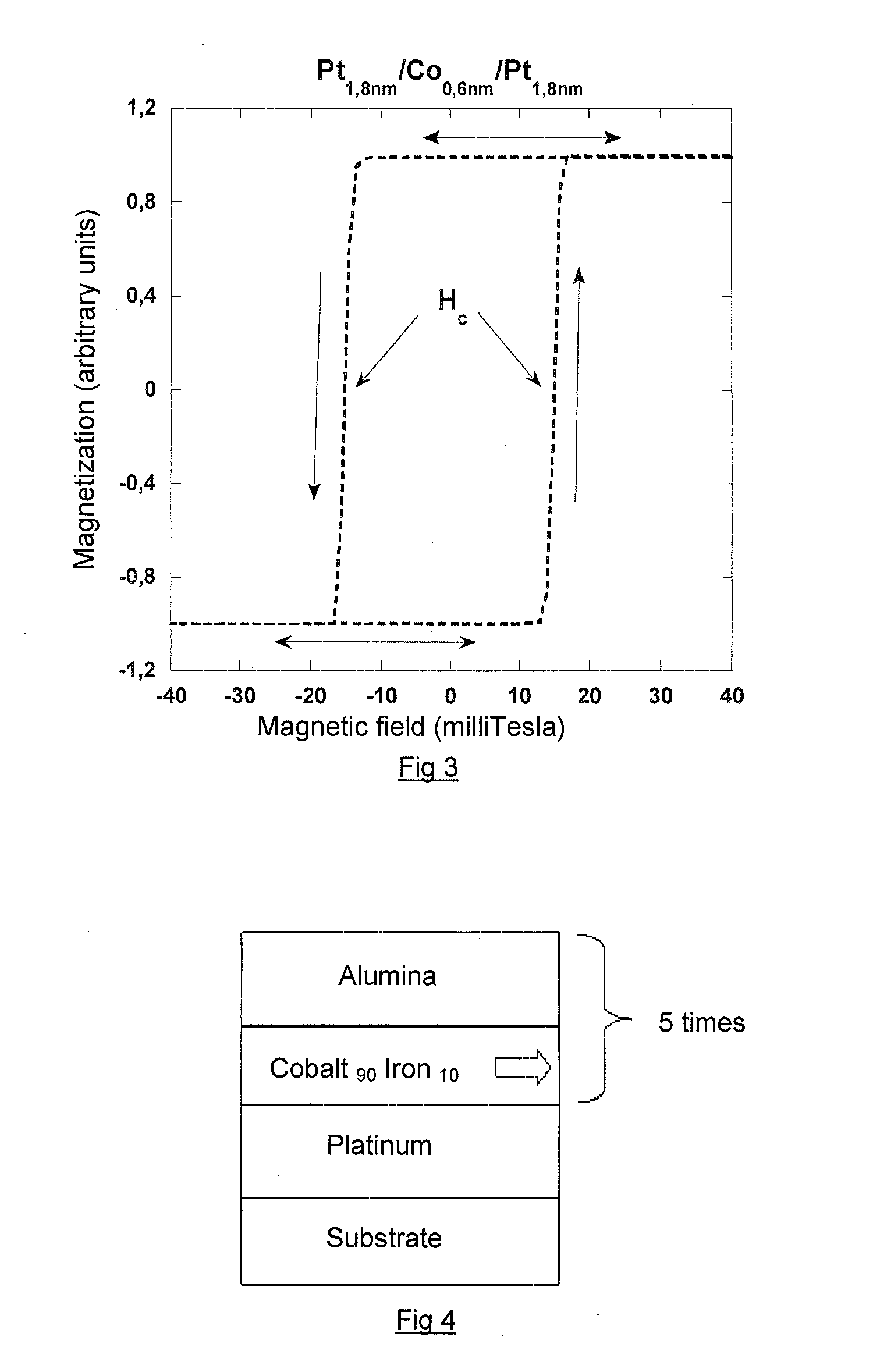
[0131]The reader is again reminded that this parameter (coercive field, as defined in relation to FIG. 3) can also be adjusted either by modifying the ...


PUM

PropertyMeasurementUnit
thicknessaaaaaaaaaa
thicknessaaaaaaaaaa
thicknessaaaaaaaaaa

Abstract

This magnetic multilayer device comprises, on a substrate, an alternating sequence of magnetic metallic layers M and oxide, hydride or nitride layers O. The number of layers M equals at least two. The layers M are continuous. There is interfacial magnetic anisotropy perpendicular to the plane of the layers at the level of the M / O interfaces.

Description

FIELD OF THE INVENTION[0001]The present invention relates to the field of magnetic materials, more especially those intended to be used firstly as magnetic field sensors or in non-volatile magnetic random-access memories used to store and read data in electronic systems or even to produce components that can be used in the field of reprogrammable logic devices.DESCRIPTION OF THE PRIOR ART[0002]One of the applications to which the present invention relates concerns magnetic devices that are used to detect magnetic fields on the basis of measuring the extraordinary Hall effect.[0003]There are two types of Hall effect: the ordinary Hall effect and the extraordinary Hall effect. The ordinary Hall effect occurs in metallic materials or doped semiconductors and is due to the Lorentz force that acts on electrons under the influence of a magnetic field. The extraordinary Hall effect occurs to a limited extent in ferromagnetic materials and is the result of diffusion of electrons due to spin...

Claims


Application Information

Patent Timeline
Patent Type & Authority Applications(United States)
IPC IPC(8): G11C11/15H01F7/02C23C14/34
CPCB82Y25/00H01F10/3286G01R33/0322G01R33/0325G01R33/07G01R33/093H01F10/30H01F10/3236H01F10/3254H01F41/18H01F41/30H01L43/06H01L43/10H01L43/14G11C11/18G11C11/5607Y10T428/115B82Y40/00H10N52/00H10N52/01H10N50/85
Inventor RODMACQ, BERNARDAUFFRET, STEPHANEDIENY, BERNARDMORITZ, JEROME
Owner COMMISSARIAT A LENERGIE ATOMIQUE ET AUX ENERGIES ALTERNATIVES
Why Eureka
Try Eureka