Ubiquitous connectivity and control system for remote locations

a remote location, connectivity technology, applied in the direction of data switching network, instruments, eavesdropping prevention circuits, etc., can solve the problems of inability to maintain the full functions of the appliance year round, inability to meet the needs of users, etc., to eliminate limitations, immobility, and inopportunities

a remote location, connectivity technology, applied in the direction of data switching network, instruments, eavesdropping prevention circuits, etc., can solve the problems of inability to maintain the full functions of the appliance year round, inability to meet the needs of users, etc., to eliminate limitations, immobility, and inopportunities

US6990335B1Inactive Publication Date: 2006-01-24UBIQUITOUS CONNECTIVITY

Image

  • Ubiquitous connectivity and control system for remote locations
  • Ubiquitous connectivity and control system for remote locations
  • Ubiquitous connectivity and control system for remote locations

Examples


Embodiment Construction

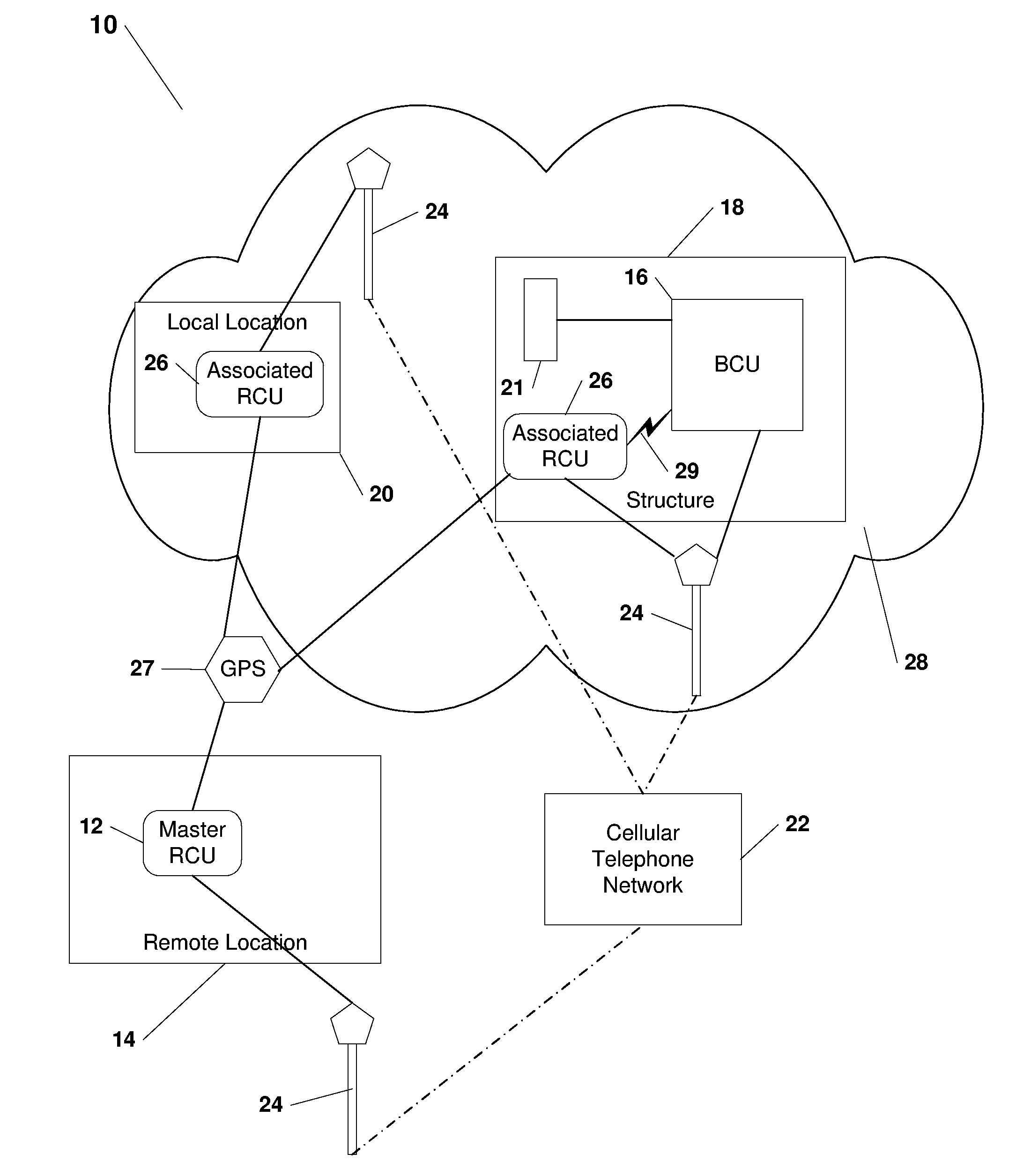
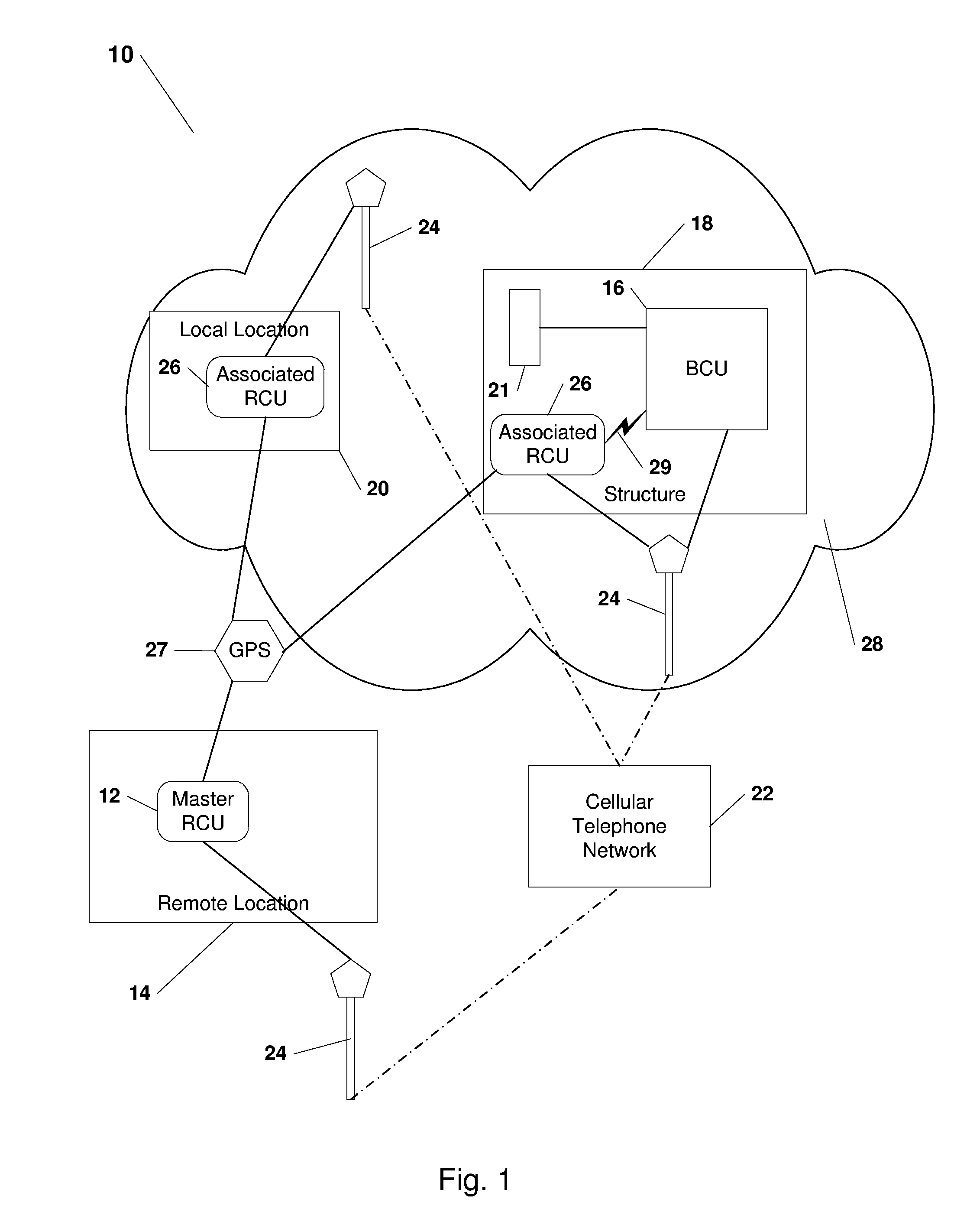
[0020]Referring to the drawings, FIG. 1 illustrates a ubiquitous connectivity and control system 10 wherein a master remote control unit 12 at a geographically remote location 14 on demand interfaces with a base control unit 16 in a structure 18 to monitor and control associated devices 21 thereat through a short message and / or the data bearer cellular telephone network 22 including control towers 24. The system 10 further includes associated control units 26 that are enabled by the base control unit 16 to undertake select monitoring and controlling activities in a proximate area 28. Associated control units 26 and the master control unit 12 utilize the global position network 27 and / or the cellular telephone network 22 and towers 24 in order to determine their geographical locations 14, 20 and report this information back to the base control unit 16 using the short message and / or data bearer services of the cellular telephone network 22 and control towers 24.

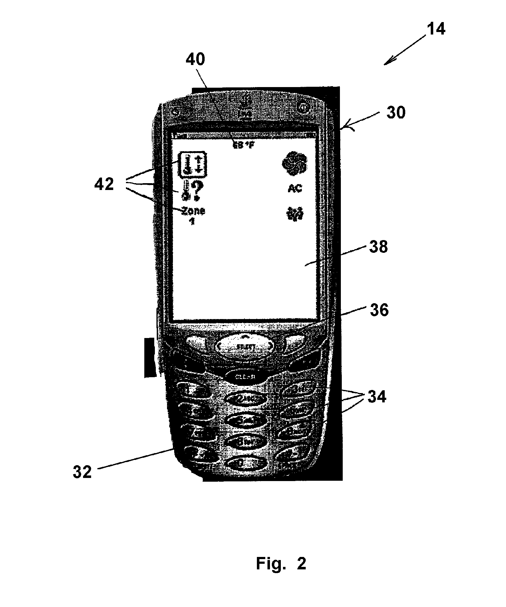
[0021]Referring to FIG....


PUM


Abstract

A thermostat control system for monitoring and controlling environmental characteristics of a building includes a base station unit and a remote access unit continuously interfacing through instant wireless private direct connectivity. The system also includes a plurality of sensors that measure the environmental characteristics and provide the thermostat unit with the measurements.

Description

RELATED APPLICATION[0001]This application claims the benefit of U.S. Provisional Application No. 60 / 522,887, filed Nov. 18, 2004, in the name of Charles Shamoon and entitled “Ubiquitous Connectivity and Control System for Remote Locations”.FIELD OF THE INVENTION[0002]The present invention relates to a remote monitoring and control system for an environment. More specifically, the system relates to on demand bidirectional communication between a remote access unit and a multifunctional base control unit in a geographically remote location.BACKGROUND OF THE INVENTION[0003]In addition to a main residence, modern times provide people and families with vacation homes that are geographically remote from the regular places of residence. Also, owners of businesses generally have their place of business remote from their residence. These structures tend to be affected by changes in environmental characteristics, either natural (i.e., weather conditions), or non-natural (i.e., vandalism, brea...

Claims


Application Information

Patent Timeline
24 Jan 2006
Publication
US6990335B1
IPC
H04M3/00; H04M1/72403; H04M1/72415; H04W48/08; H04W64/00; H04W84/10; H04W88/08
CPC
G01D21/00; H04L12/2825; H04L12/2827; H04M1/72533; H04M3/42; G08C17/02; H04W88/08; G08C2201/42
Inventors
SHAMOON, CHARLES G.; SHAMOON, DEBORAH H.