
Electrically controlled apparatus

a technology of electric control and control apparatus, which is applied in the direction of electric controllers, digital output to print units, instruments, etc., can solve the problems of inconvenient use, large difficulty for administrators and common users to know the operating status, and inaccurate giving of new instructions, so as to prevent the operation of each component. , the effect of preventing the operation of each componen

Inactive Publication Date: 2006-01-24
SHARP KK
View PDF21 Cites 122 Cited by
  • Summary
  • Abstract
  • Description
  • Claims
  • Application Information

AI Technical Summary

Benefits of technology

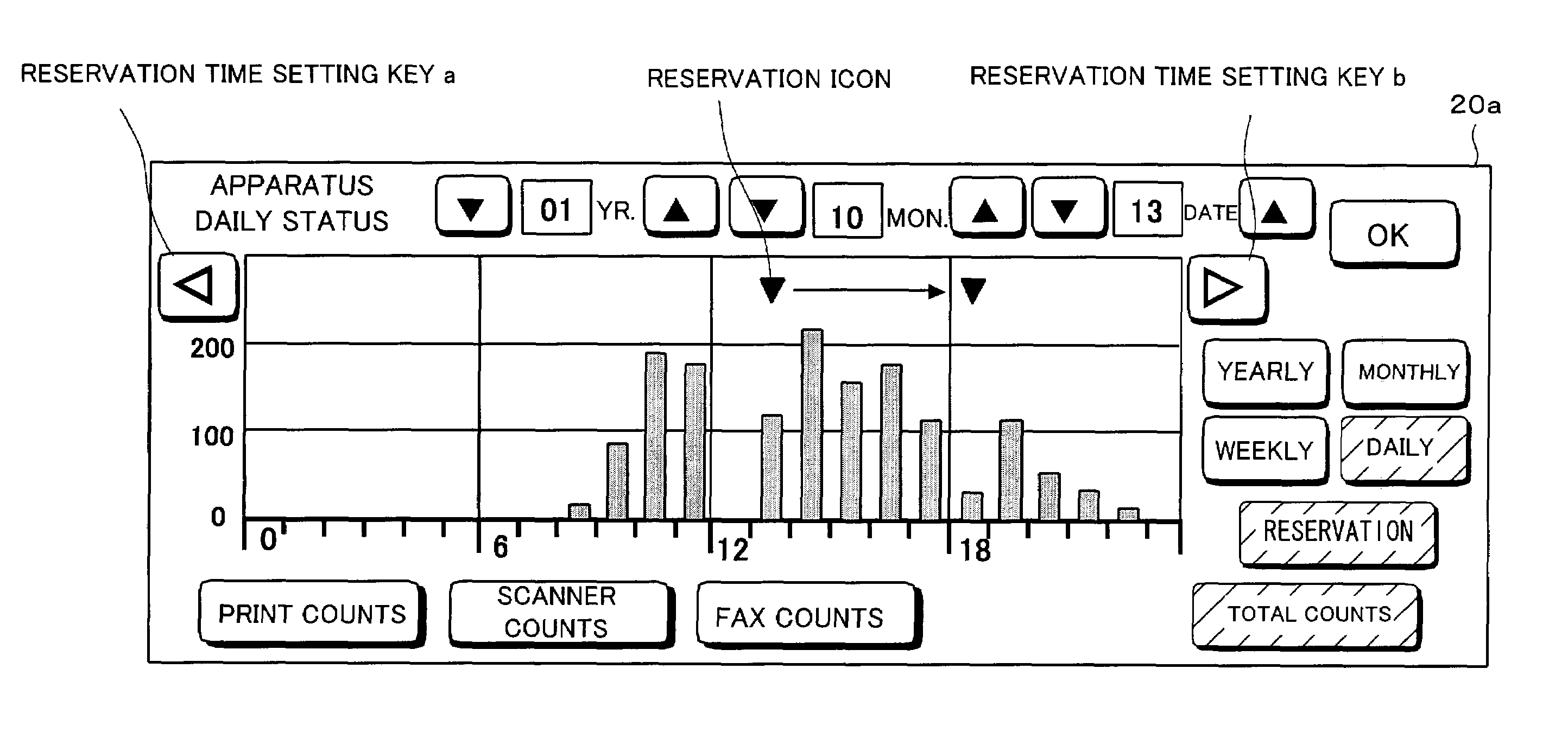
[0010]According to this configuration, by the provision of the processing section that creates graphic display of the operating status of each component, the operating status of each component can be graphically displayed. This enables a user to visually confirm a load on each component and its surrounding environment, allowing the user to give new instructions or consider other options based on the graphically displayed operating status.
[0011]The foregoing configuration is also advantageous for the administrators. Namely, it makes it easier for the administrators to perform daily management, such as replenishing of expendables such as paper or a developer, so as to prevent operations of each component from being arrested.
[0013]According to this configuration, the operating status of the apparatus complex is graphically displayed for each processing unit (scanner unit, printer unit, fax unit, etc.). This enables a user to visually confirm a load on each processing unit and its surrounding environment.
[0014]Thus, the foregoing configuration allows the user to more accurately give new instructions or consider other options based on the graphically displayed operating status of each processing unit. The foregoing configuration is also advantageous for the administrators. Namely, it makes it easier for the administrators to perform daily management, such as replenishing of expendables such as paper or a developer, so as to prevent operations of each component of each processing unit from being arrested.
[0016]According to this configuration, the operating status of each of the processing modes of the apparatus complex is graphically displayed. This enables a user to visually confirm a load on each processing mode and its surrounding environment, allowing the user to give new instructions or consider other options based on the graphically displayed operating status of each processing mode. The foregoing configuration is also advantageous for the administrators. Namely, it makes it easier for the administrators to perform daily management, such as replenishing of expendables such as paper or a developer, so as to prevent operations of each component of each processing mode from being arrested.

Problems solved by technology

However, the electronically controlled apparatus that is shared by multiple users, or that with a plurality of modes (plural paths of image entry) is associated with a problem.
Arresting operations of the electronically controlled apparatus, however, is inconvenient for the users and management of the apparatus should ideally be carried out to cause as few problems as possible for the users.
Such a monitoring system, however, poses a great difficulty both for the common users and the administrator to know the operating status because the system only displays a list.
This is troublesome for the user of the apparatus when the regular inspection needs to be carried out at the time when the activity rate (operating status) of the electronically controlled apparatus is high.

Method used


Image

  • Electrically controlled apparatus
  • Electrically controlled apparatus
  • Electrically controlled apparatus

Examples


first embodiment

[0043][First Embodiment]

[0044]One embodiment of the present invention is described below with reference to FIG. 1 through FIG. 25.

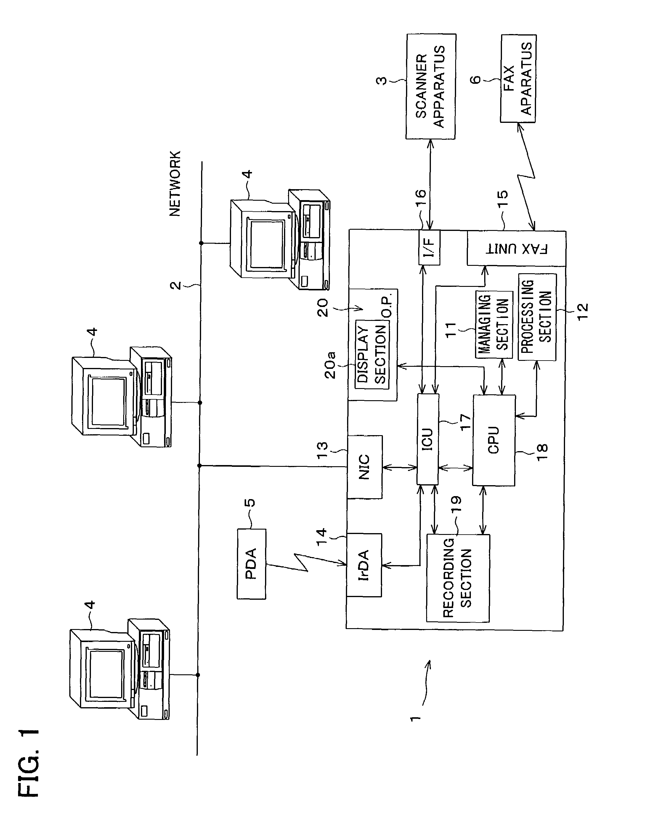
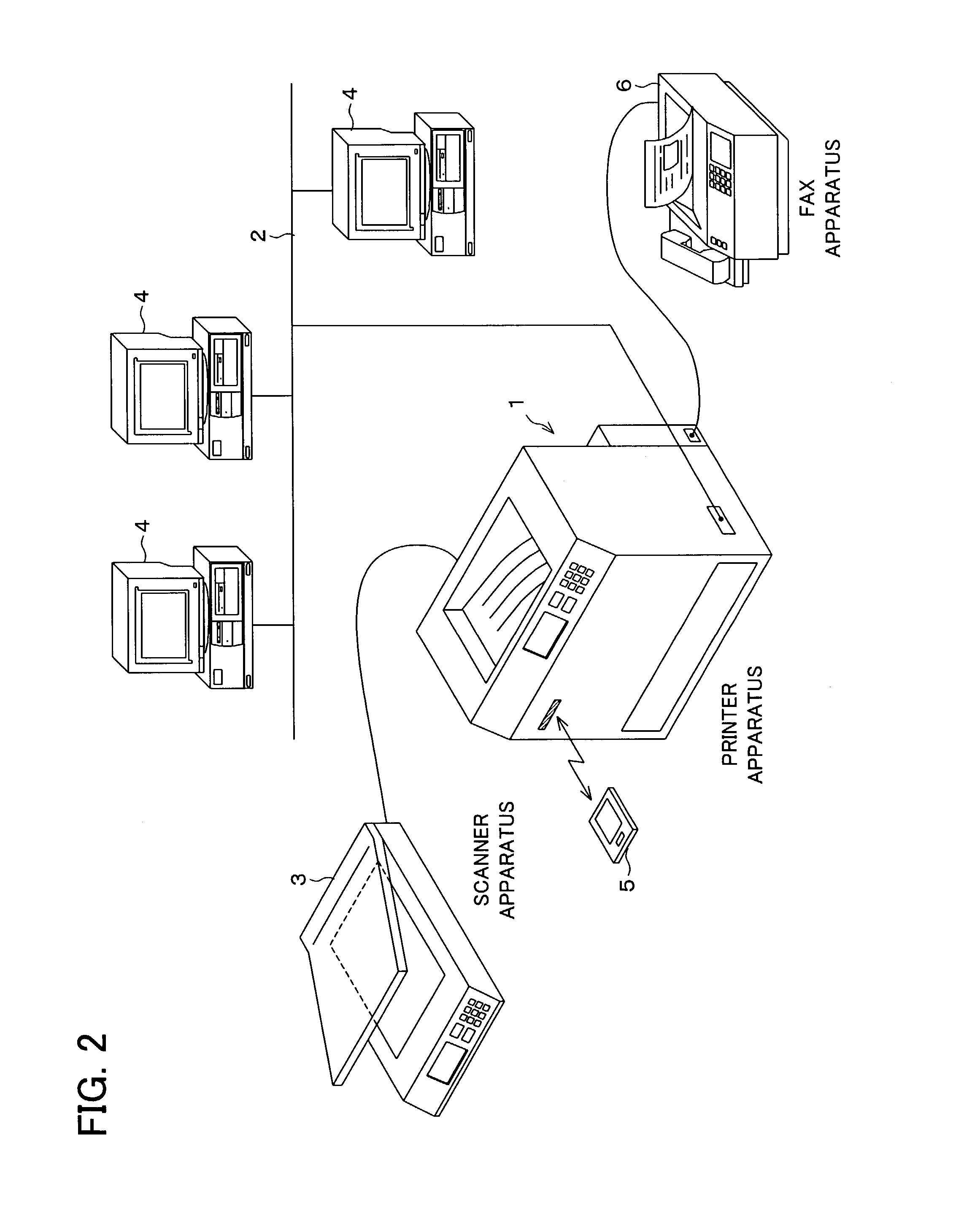
[0045]One application of a managing system of an electronically controlled apparatus according to the present invention is shown, for example, in FIG. 2. In this example, a printer apparatus 1 connected to a network is provided as the electronically controlled apparatus.

[0046]The printer apparatus 1, which is the core of the present managing system, is connected, at all times or upon request, to various types of electrical apparatuses or devices, such as a scanner apparatus (processing unit) 3, a personal computer 4, a PDA terminal 5, and an externally provided facsimile (FAX, processing unit) apparatus 6, via communication paths 2 such as a network. The printer apparatus 1 is able to successively make prints of image data that are transmitted from these electrical apparatuses or devices.

[0047]The managing system of the present invention, working in this ...

second embodiment

[0074][Second Embodiment]

[0075]In a Second Embodiment of the present invention, the processing section 12 of the printer apparatus 1, based on the operating status monitored data of the apparatus managed by the managing section (managing table) 11, creates graphic display of an operating status of each processing unit, such as the scanner apparatus (scanner unit) 3 and the FAX unit 15, of an apparatus complex connected to the printer apparatus 1, in addition to creating graphic display of an operating status for the printer apparatus 1, so that the operating status can be grasped at a glance, as shown in FIG. 11 through FIG. 13.

[0076]As described above, operating the current status key 20c of the operator panel 20, when accompanied by a request for graphic display of the operating status of the apparatus complex, causes the processing section 12 to create graphic display based on information managed by the managing section 11. The information of the operating status in the form of g...

third embodiment

[0087][Third Embodiment]

[0088]In a Third Embodiment of the present invention, a user is able to make a reservation for a new print job, observing the graphic display of the operating status of the printer apparatus 1.

[0089]A reservation for a new job can be entered by operating the “RESERVATION” key (reservation instructing section) that is provided substantially in the right half of the display screen of the display section 20a in the operator panel 20 of FIG. 5 (the same for the screens of FIG. 6 through FIG. 9).

[0090]For example, when the “RESERVATION” key is operated in the graphic display of the operating status in the time scale of a day as shown in FIG. 10, the screen displays reservation instructing display as shown in FIG. 14. The CPU (reservation mark displaying section) 18 displays a reservation icon at a time location that corresponds to the current time. In case where a reserved job already exists, another reservation icon indicating “RESERVED” is also displayed.

[0091]T...


PUM


Abstract

An electronically controlled apparatus of the present invention includes: an input-output section, which electronically processes and outputs input data; a control section, which electronically controls the input-output section according to operating status data of each component of the input-output section; a managing section, which monitors the operating status data of each component of the input-output section, so as to store and manage the operating status data with corresponding time information of the operating status data; and a processing section, which creates graphic display of the operating status data in a given time scale according to the operating status data and the time information. With the electronically controlled apparatus, it becomes easier to manage regular inspections and replenishing expendables, without lowering an activity rate.

Description

FIELD OF THE INVENTION[0001]The present invention relates to an electronically controlled apparatus that monitors an operating status of each apparatus component so as to display an operating status of the apparatus, as required, in the form of graphic display (level display) that is highly recognizable and allows the electronically controlled apparatus to be easily managed.BACKGROUND OF THE INVENTION[0002]In today's network environment, an electrically controlled apparatus connected to a network is often shared by multiple users. An example of such an electrically controlled apparatus is a printer connected to a network. Such a printer operates to receive a series of jobs that were requested for output by multiple clients and the printer prints out the jobs in the order they were received. This is a convenient way of automatically making prints of requested jobs.[0003]In the last years, there has been commercialized a complex system that provides a scanner (copier), a facsimile, an...

Claims


Application Information

Patent Timeline
IPC IPC(8): G06F19/00G06T11/20G05B15/00G06F17/00B41J29/42G03G21/00G05B23/02G06F3/00G06F3/12G06F3/14G06F15/163G06F15/17G09G5/00H04N1/00
CPCH04N1/0035G06F3/1285H04N1/00832G06F3/1204G06F3/1229G06F3/1273H04N1/00477H04N2201/0094H04N2201/3202Y10S715/961Y10S715/966Y10S715/969Y10S715/963Y10S715/967Y10S715/974Y10S715/965G06F3/1217
Inventor NOMURA, TATSUOYOSHIURA, SYOUICHIROUYOSHIMOTO, TSUTOMU
Owner SHARP KK
Learn More