
Low fluid level indicator for hydration bladder

a technology of low fluid level and hydration bladder, which is applied in the direction of lighting and heating equipment, instruments, and domestic cooling equipment, etc., can solve the problems of limited water source availability, water system as compared to water bottles, and monitoring of fluid levels

Inactive Publication Date: 2006-01-31
GILLANDERS DAVID DOUGLAS
View PDF14 Cites 45 Cited by
  • Summary
  • Abstract
  • Description
  • Claims
  • Application Information

AI Technical Summary

Benefits of technology

"The invention is about monitoring the volume of a hydration bladder by measuring changes in its shape as liquid is added or withdrawn. This is done using sensors that detect the distance between the bladder walls or the shape change in the bladder wall as liquid is added or withdrawn. The information collected is processed and reported to the user to help them understand the relative fluid level of the bladder."

Problems solved by technology

However, a major disadvantage of hydration systems as compared to water bottles, is the monitoring of fluid levels.
Additionally, in the case of backpacking in wilderness areas, quite often there is a limited availability of sources for water.
Since such sources often do not contain safe drinking water, the water must be filtered or treated with chemicals prior to drinking.
Both these activities result in a time period elapsing before the water may be consumed.
Additionally, hydration bladders are not in a constant vertical position due to their being attached to the body of the user, and are subject to many degrees of motion.
Further complicating this is the bladder's susceptibility to external pressure from other items loaded into a backpack.
The operation of a personal hydration bladder is controlled by the user's mouth and the amount of liquid withdrawn naturally varies significantly, making Griffiths' liquid dispenser unsuitable.
This method is impractical because bladders are often used in the outdoors and refilled or partially refilled from natural water sources, through filter / pump systems, or from additional containers of fluid, the exact volume of which may not be known.
Perkins' meter system is “blind” to the amount added to the bladder and therefore cannot provide any warning as to when the bladder will empty.
Additional disadvantages to flow meter systems are complexity, high cost, and failure potential from sub-freezing temperatures.
Because they use invasive sensing, i.e., devices immersed in the fluid, and must be held to tight tolerances due the low flow rates encountered in this application, flow meter systems are also vulnerable to fouling from nutritional additives and sports drinks, which are often mixed into the water.
The interactive hydration prompt feature of flow meter systems has merit, but has limitations in that the system does not account for ambient temperature, relative humidity, actual perspiration loss, and exertion level of the user—all of which are determinants of optimal re-hydration rates.
When the field is removed, the reeds lose their magnetic properties and separated through their own spring tension, breaking the electrical circuit.
The devices discussed above would add an undesirable amount of bulk and weight to the payload carried by the user.

Method used


Image

  • Low fluid level indicator for hydration bladder
  • Low fluid level indicator for hydration bladder
  • Low fluid level indicator for hydration bladder

Examples


Embodiment Construction

—FIGS. 1, 2, 3, 4, 5, 6, 10, 11

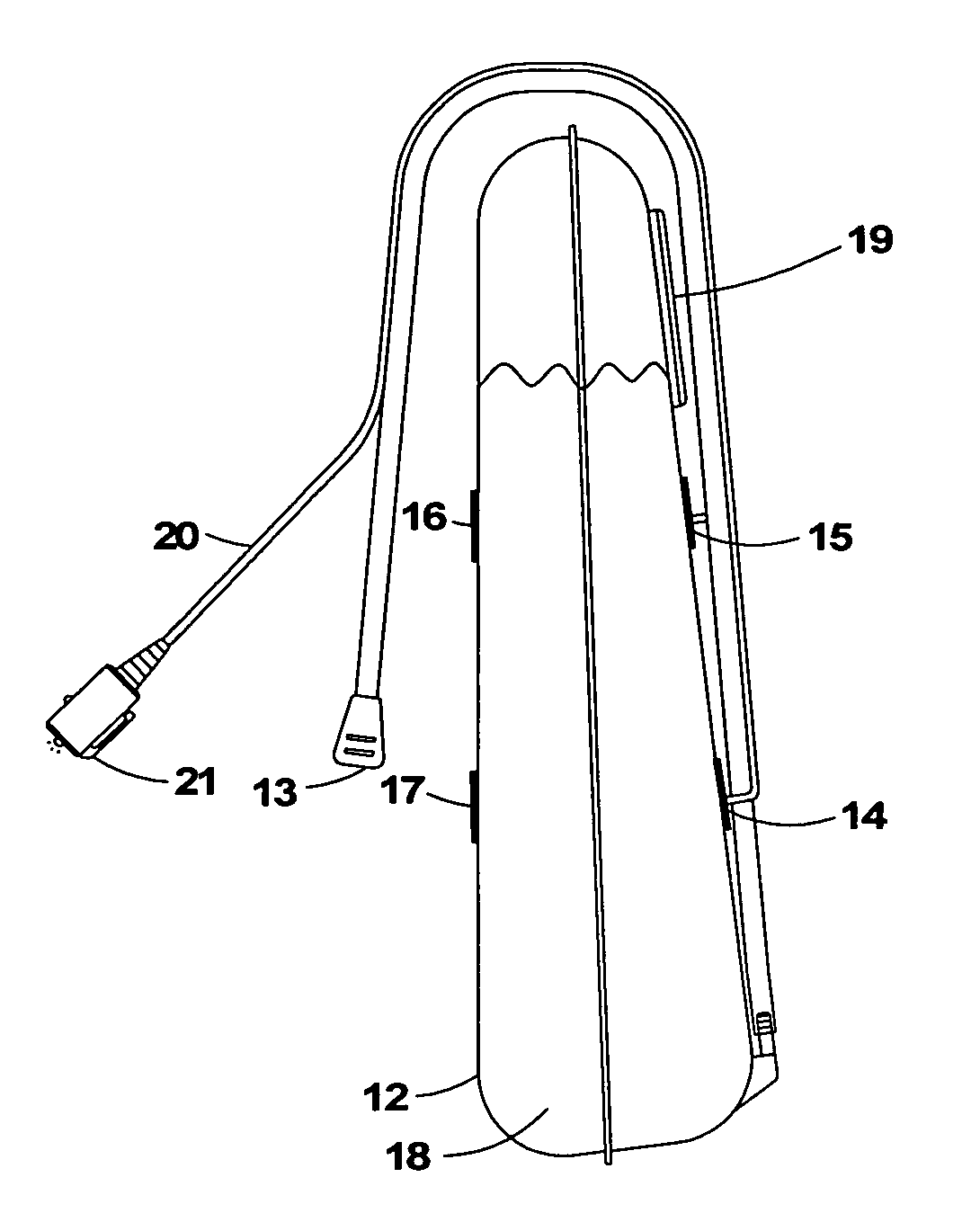
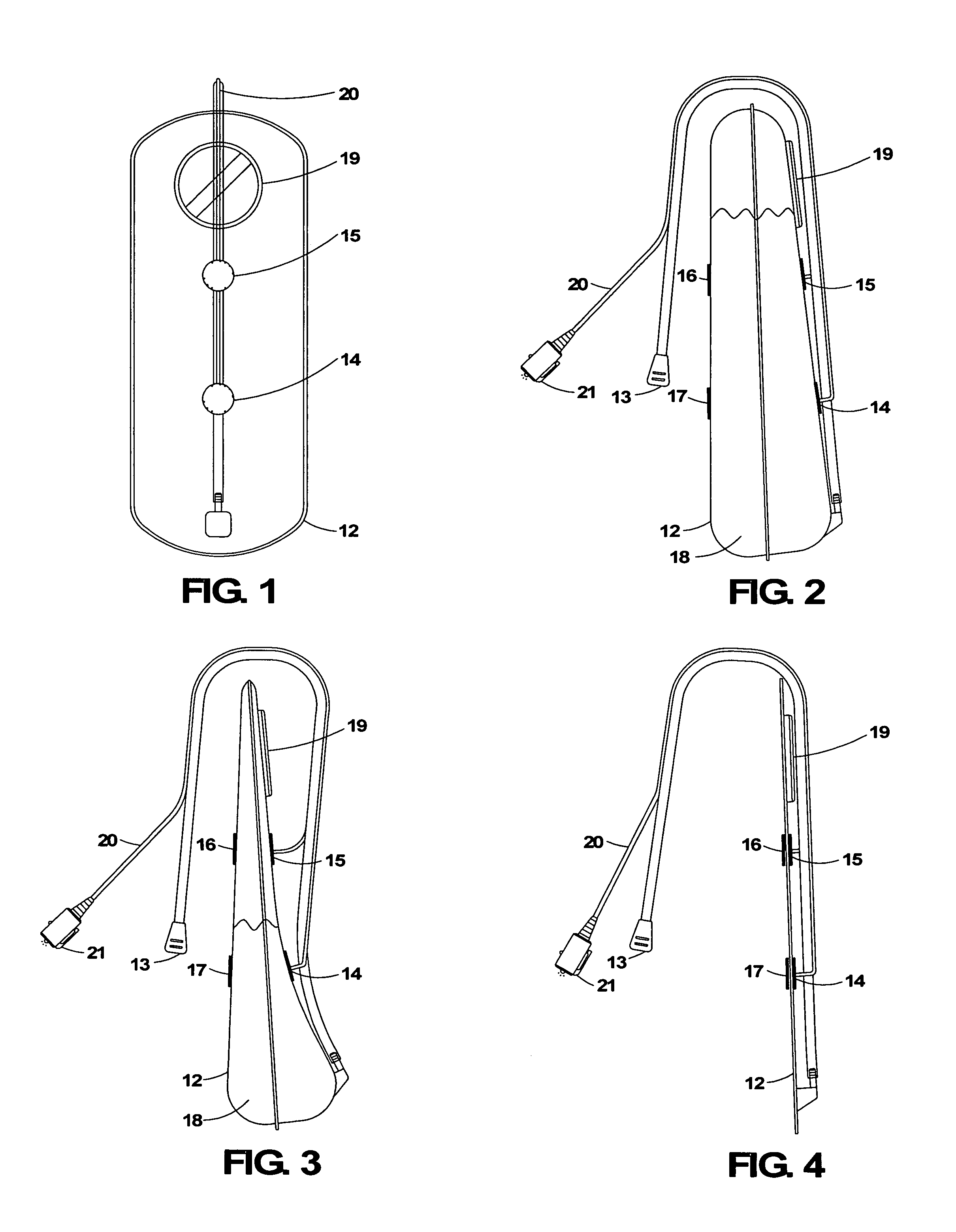
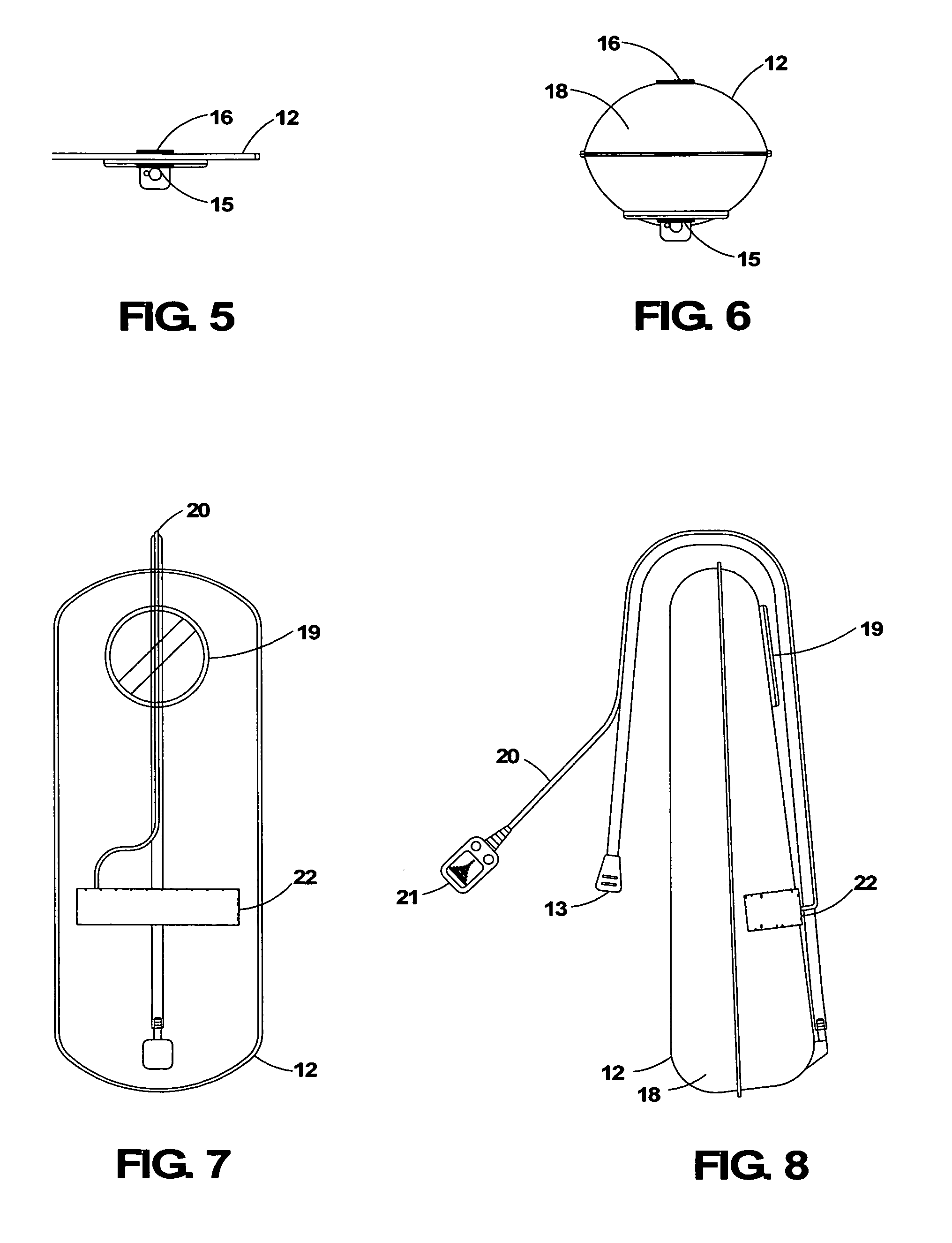
[0042]A prior-art hydration bladder 12 (FIG. 1) with a mouthpiece and drinking tube 13 (FIG. 2) and filler cap 19 (FIG. 1). The bladder is typically constructed of flexible urethane material and has a generally rectangular shape has length and width dimensions of approximately 18 inches by 7 inches, depending on the designated fluid volume capacity. The bladder has lower and upper magnetically actuated reed switches 14 and 15 (FIG. 1) affixed to the exterior of one side of the bladder. Corresponding upper and lower magnets 16 and 17 (FIG. 2) are affixed on the exterior opposing side of the bladder, proximal to the reed switches. This arrangement provides two alert levels. One reed switch and one magnet may be used as well, for a single-alert level. The desired levels of alert, i.e., amount of remaining fluid 18 (FIG. 2) in the bladder upon alert, are determined by the placement of the reed switches and magnets. The amount of fluid remaining when the re...


PUM


Abstract

A method for indicating the relative fluid level of a personal hydration bladder, and for alerting the user that the bladder has been depleted to a predetermined level or levels. A non-invasive sensor detects changes in the bladder geometry and transmits the information to a indicating unit worn by the user.

Description

BACKGROUND[0001]1. Field of Invention[0002]This invention relates generally to the measurement or quantification of a volume of liquid, especially as used in personal hydration systems for individuals for carrying and supplying drinking water and electrolyte replacement fluids.[0003]2. Prior Art[0004]Personal hydration systems generally comprise a flexible bladder and a drinking tube, and are usually carried in a backpack or waist pack. A product popular with hikers, cyclists and skiers is sold under the trademark CamelBak, by CamelBak Products, Inc. of Petaluma, Calif. Numerous competitors offer similar products. To prevent leakage, the bladder is usually not vented and therefore collapses upon itself as the fluid is withdrawn. A flexible tube connects to the bladder and enables the user to withdraw fluid by creating suction on the other end of the tube. There is usually a mouthpiece with a valve attached to the tube to facilitate the withdrawal of the fluid into the user's mouth. ...

Claims


Application Information

Patent Timeline
Patent Type & Authority Patents(United States)
IPC IPC(8): G01F22/00B65D37/00A45F3/20G01F23/00
CPCA45F3/20G01F22/00G01F23/0007G01F23/00H01H36/0046
Inventor GILLANDERS, DAVID DOUGLAS
Owner GILLANDERS DAVID DOUGLAS
Learn More