Planar light source unit and display device

a light source unit and display device technology, applied in the field of planar light source units and display devices, can solve the problems of insufficient study, insufficient light use efficiency and luminance, and insufficient study, and achieve the effect of enhancing luminance characteristics and high light use efficiency

Inactive Publication Date: 2006-01-31
MITSUBISHI ELECTRIC CORP
View PDF13 Cites 67 Cited by
  • Summary
  • Abstract
  • Description
  • Claims
  • Application Information

AI Technical Summary

Benefits of technology

[0012]Accordingly, an object of the present invention is to provide a planar light source u...

Problems solved by technology

Not enough study, however, has been done on the relationships between particular prism sheets and light guide p...

Method used


Image

  • Planar light source unit and display device
  • Planar light source unit and display device
  • Planar light source unit and display device

Examples


Embodiment Construction

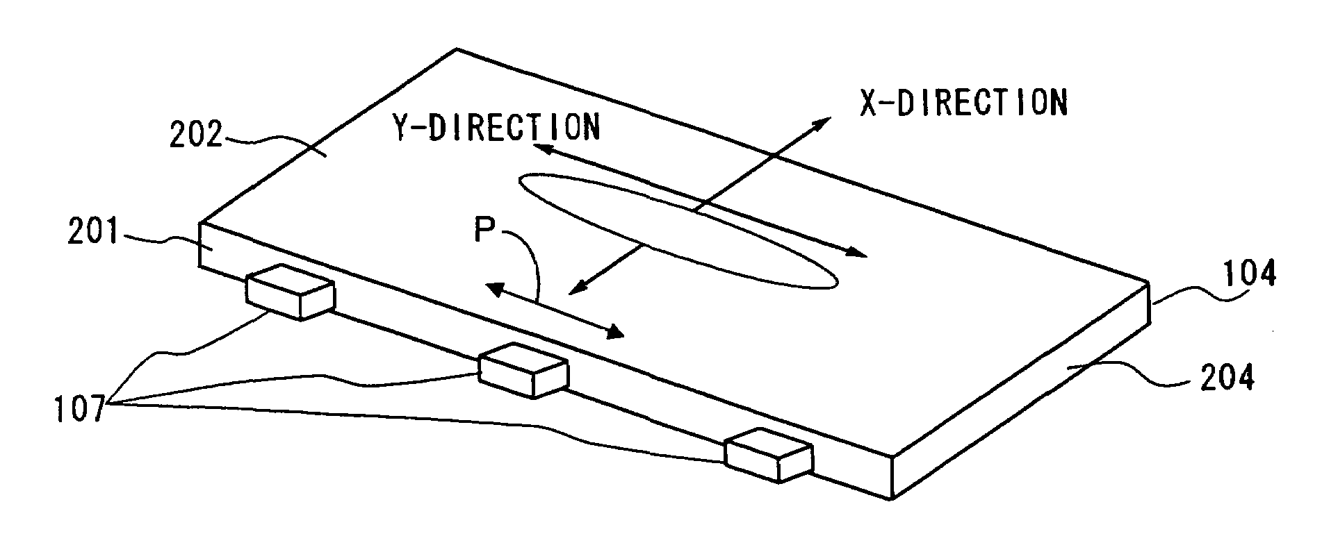
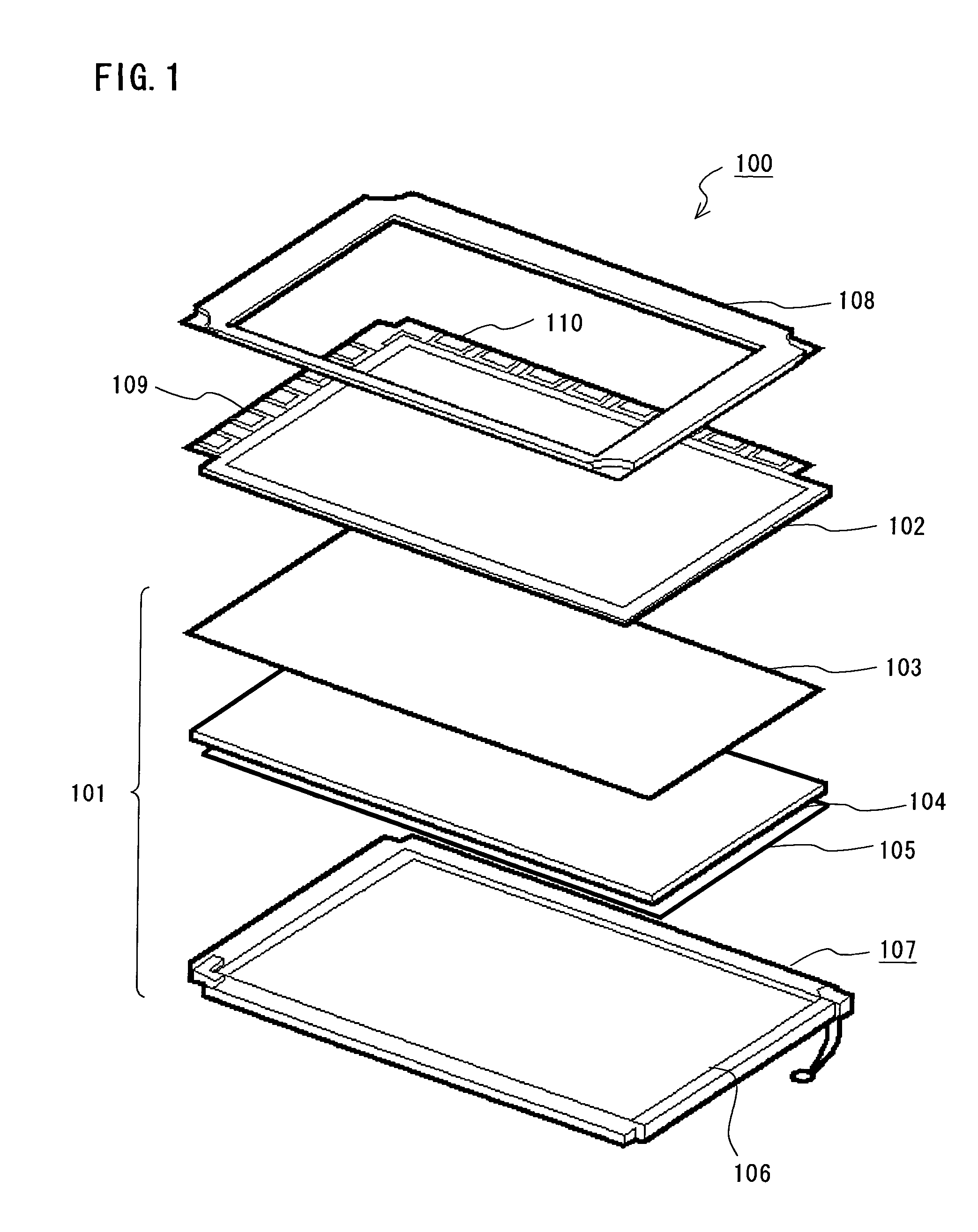
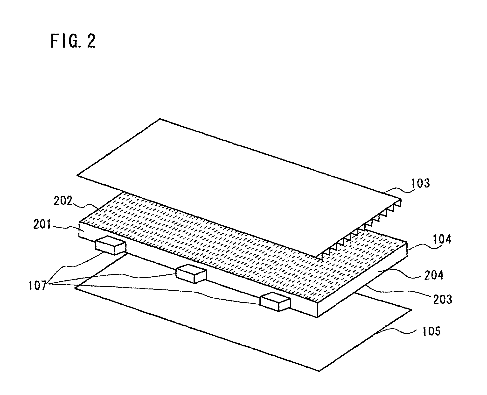
[0023]In the following, possible embodiments to which the present invention may be applied will be explained in detail. A backlight unit according to a preferred embodiment of this invention has a light guide plate and a prism sheet placed so that a prism surface where prism structures are formed faces the light guide plate. An anisotropic diffraction grating is formed on the upper or bottom surface of the light guide plate. The anisotropic diffraction grating is preferably a hologram pattern. The surface of the light guide plate where the hologram pattern is formed will be referred to hereinafter as a hologram surface. The backside of the hologram surface has a surface structure to control a light exit angle. An apex angle of each of the prism structures is larger than 65 degrees and smaller than 68 degrees. From the invention described in the following, it will be obvious that the embodiments of the invention may be varied in many ways. Such variations are not to be regarded as a ...


PUM


Abstract

A light guide plate has a hologram pattern on a light exit surface. The hologram pattern anisotropically diffuses light in the direction parallel with a light incident surface of the light guide plate. On a back surface of the light guide plate are formed mirror-polished prism structures extending parallel with the light incident surface. A downward-pointing prism sheet with a given prism apex angle is placed on the light exit surface of the light guide plate. The use of the downward-pointing prism sheet together with the light guide plate having the anisotropic diffusion hologram pattern integrally formed thereon produces a liquid crystal display device with enhanced luminance properties.

Description

BACKGROUND OF THE INVENTION[0001]1. Field of the Invention[0002]The present invention relates to a planar light source unit and a display device, and more particularly, to a planar light source unit and a display device having a light guide plate with an anisotropic diffraction grating, and a downward-pointing prism sheet.[0003]2. Description of the Related Art[0004]Liquid crystal display devices are widely used as image display devices for personal computers and various types of monitors. The liquid crystal display devices generally include a liquid crystal display panel and a backlight unit mounted on the back of the panel. The liquid crystal display panel displays images by controlling transmission of light. Among several types of liquid crystal display devices is one employing a sidelight (or edgelight) type backlight unit. A light source is positioned at the side of a display surface in this type of liquid crystal display device so as to make the device assembly as thin as poss...

Claims


Application Information

Patent Timeline
IPC IPC(8): F21V7/04G02F1/1335G02B6/00F21V8/00F21Y101/02G02B5/04G02B5/18G02F1/13357
CPCG02B5/1866G02B6/0053G02B6/0038G02B6/0036G02F1/1335
Inventor KOKOGAWA, TORU
Owner MITSUBISHI ELECTRIC CORP
Why Eureka
Try Eureka