Spatially directed ejection of cells from a carrier fluid

a technology of carrier fluid and ejection device, which is applied in the field of ejection of cells from a fluid, can solve the problems of not being able to sort cells into individual array sites by size, requiring costly and detailed microfabrication, and not being able to achieve the current employed methods of manipulating cells, etc., to achieve the effect of forming arrays of single live cells more quickly, flexibly and economically, and reducing the number of cells

Inactive Publication Date: 2006-01-31
LABCYTE
View PDF27 Cites 22 Cited by
  • Summary
  • Abstract
  • Description
  • Claims
  • Application Information

AI Technical Summary

Benefits of technology

[0011]In yet another aspect, the invention provides a method of forming arrays of single live cells more rapidly, flexibly, and economically than by approaches requiring the use of holes or physical wells together with independent channel-based microfluidic delivery.

Problems solved by technology

No currently employed methods of manipulating cells permit making an ordered array of single cells on a planar substrate surface.
Further, no method of sorting cells into individual array sites by size exists other than that of controlling physical hole or well size as described by Weinreb et al., supra, to permit cell populations of differing size to enter and be contained in non-planar holes or wells.
Such systems may be easily altered to permit tests on individual cells or a large number of cells simultaneously, but they require costly and detailed microfabrication.
The site density of such arrays is limited by the need to make individual wells according to demanding physical specifications, such as minimum well wall thickness for physical integrity and additional space for the channels themselves.
No method or device is known to exist for manipulating individual cells by ejecting them from a fluid onto a substrate surface without killing the cells.

Method used


Image

  • Spatially directed ejection of cells from a carrier fluid
  • Spatially directed ejection of cells from a carrier fluid
  • Spatially directed ejection of cells from a carrier fluid

Examples


example 1

[0081]Acoustic Ejection of Monocytes onto a Substrate to form an Array:

[0082]Rabbit polyclonal-Ab against human MHC (displayed on all cells) is generated and a single clone is selected that binds an MHC epitope common to all humans rather than to the epitopes specific to individuals. A substrate is functionalized with the mAb by routine methods. Monocrystalline Si is chosen as the substrate because of the plethora of known methods for functionalizing Si. A channel 25 μm wide, 25 μm deep, and about 3 cm long, open on top for the last 0.5 cm, is utilized to economize on time spent searching for cells to eject. The channel is fabricated of an HF-etched glass plate heat fused to a cover glass plate by routine microfabrication techniques.

[0083]The channel is fluidically connected by routine methods to a fluid column to which the cell suspension is added. The dimensions of the column allow 5 mL of fluid carrier and cells to be added, so that a sufficient column pressure exists to initiate...

example 2

[0088]Human Airway Epithelium (HAE) Cell Array for Studying Airway Immune and Inflammatory Response:

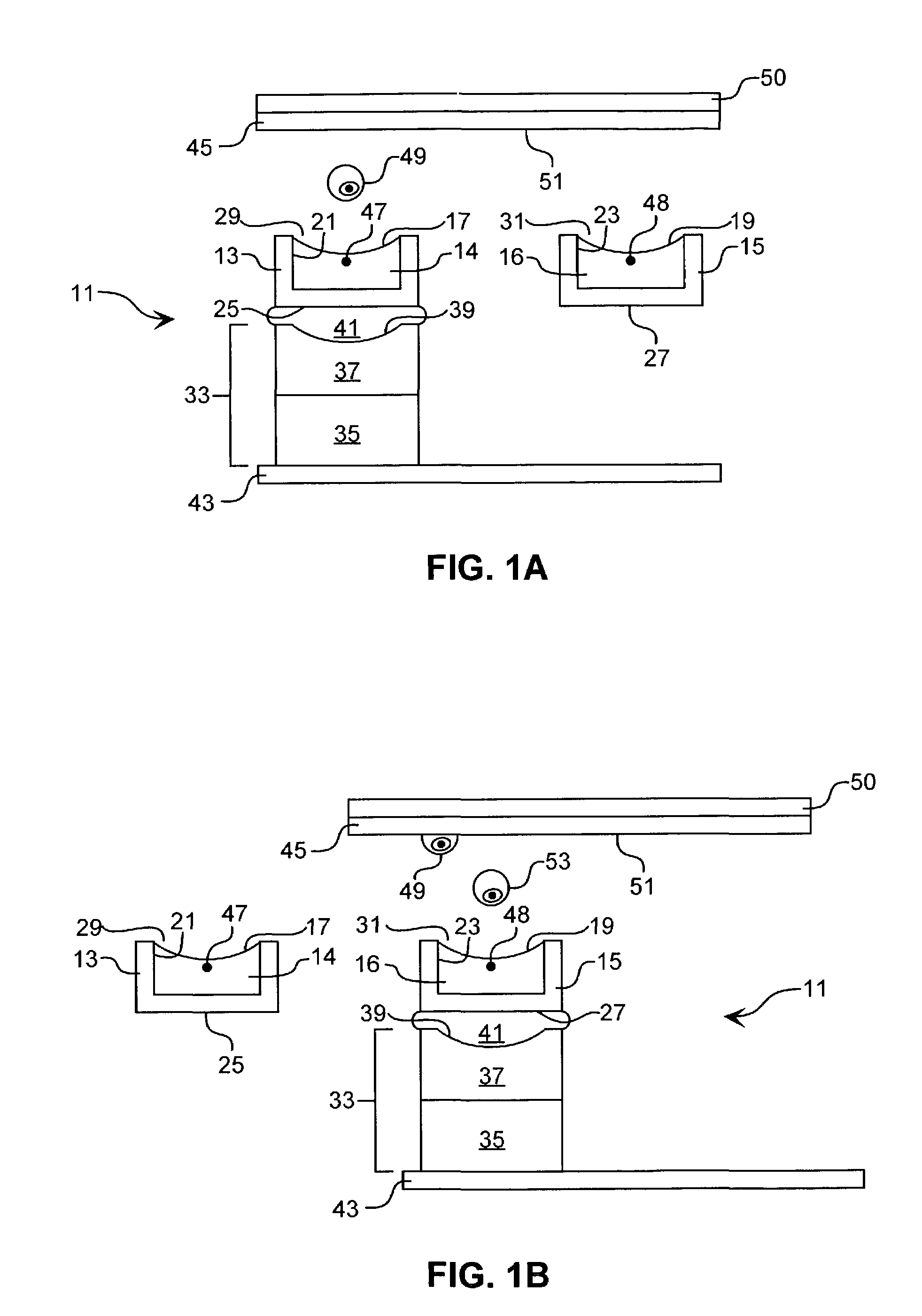
[0089]The method of the preceding example is adapted to HAE cells by providing a channel having appropriate dimensions (just larger than the HAE cells). Alternatively, the width of the channel is just wider than the cells; to permit faster loading, the depth is approximately three times the diameter of the cells and a ramp, as depicted in FIG. 5D, is employed in the channel flow path just prior to the channel region, which is open. Alternatively, a photon field, as may be provided by a laser commonly used in optical tweezers, may be employed to force the cells close to the surface. HAE cells may be obtained by routine biopsy and cultured. Before being loaded for ejection they must be disaggregated by conventional tissue culture methods and then suspended as individual cells.

[0090]The experiments may be conducted under conditions that permit cell division. The need for the preceding as...

example 3

[0091]HAE Cell Array for Studying Individual Susceptibility to Mutagenesis as a Proxy for Carcinogenesis:

[0092]The method of the preceding example is adapted to permit exposing the arrayed HAE cells to chemical and other mutagens, such as heat and radiation. Genetic damage is measured at different times after the exposure is discontinued by routine methods, for example biochemical assaying of broken crosslinks and other damage to DNA. Differences in DNA repair enzyme genetics may be studied by comparing recovery (extent of reduction of damage) at various times after exposure. The well plate arrays remain useful as controls, and cells may be cultured in the well plates, or array cells may be removed and cultured, to determine whether there is actual appearance of dysplastic or neoplastic cells in subsequent cell generations after the exposure.


PUM

PropertyMeasurementUnit
diametersaaaaaaaaaa
diametersaaaaaaaaaa
thickaaaaaaaaaa

Abstract

This invention is directed to the use of focused energy, particularly focused acoustic energy, in the spatially directed ejection of cells suspended in a carrier fluid, e.g., for providing a pattern of cells on a substrate surface, such as a cellular array.

Description

CROSS-REFERENCE TO RELATED APPLICATIONS[0001]This is a continuation of U.S. patent application Ser. No. 09 / 999,166, filed Nov. 29, 2001 now U.S. Pat. No. 6,893,836, which is a continuation-in-part of U.S. patent application Ser. No. 09 / 727,391, filed Nov. 29, 2000, now abandoned.TECHNICAL FIELD[0002]This invention relates generally to the ejection of cells from a fluid, for example, onto a substrate surface to form a cellular array. More particularly, the invention relates to the use of focused acoustic energy to effect the spatially directed ejection of cells suspended in a carrier fluid. The invention additionally relates to the use of such a method for depositing cells onto a substrate surface, such as to form a patterned array of cells thereon.BACKGROUND[0003]Arrays of single living cells have been made by inserting individual cells into individual well sites or holes that are open on both the top and bottom, with the top opening large enough for a desired cell to pass through a...

Claims


Application Information

Patent Timeline
Patent Type & Authority Patents(United States)
IPC IPC(8): C12Q1/02G01N33/48B41J2/14C12M1/26C12M1/34C12M3/00C12N5/00C12N5/02G01N1/28G01N15/10G01N15/14G01N30/02G01N37/00
CPCB41J2/14008C12M47/04G01N15/1056G01N29/028G01N35/1074G01N30/02G01N2035/1039G01N2015/1081B01D2015/389C12M33/00
Inventor MUTZ, MITCHELL W.ELLSON, RICHARD N.
Owner LABCYTE
Why Eureka
Try Eureka