X-ray and neutron imaging

a technology of x-ray and neutron, applied in the field of x-ray or neutron imaging of objects, can solve the problems of limited aperture small apertures of compound refractive lenses, and limited ability

Inactive Publication Date: 2006-01-31
ADELPHI TECH INC
View PDF4 Cites 7 Cited by
  • Summary
  • Abstract
  • Description
  • Claims
  • Application Information

AI Technical Summary

Benefits of technology

[0021]The invention permits the overcoming of the problem of the compound refractive lenses that are highly limited by their apertures and, hence, by their field of view. The method permits the x-ray or neutron imaging of large objects. The invention permits the fabrication of large area arrays of compound refractive lenses that are capable of imaging large objects with either x-rays or neutrons. The invention also permits the collection, focusing or collimation of x-rays or neutrons from large-area sources. The invention permits the use of very small unit lenses of high radius of curvature, which in turn permits short focal length lens systems.

Problems solved by technology

Unfortunately, the aperture of the compound refractive lens is limited.
However, since lens shape can be made parabolic and the mechanical aperture can be made larger, the absorption aperture ra is usually the limiting aperture.
Thus the compound refractive lens' apertures are small and limited in their ability to capture the total image or collect most of the flux from sources of neutrons or x-rays.

Method used


Image

  • X-ray and neutron imaging
  • X-ray and neutron imaging
  • X-ray and neutron imaging

Examples


Embodiment Construction

1. Three-dimensional (3-D) Lens Array

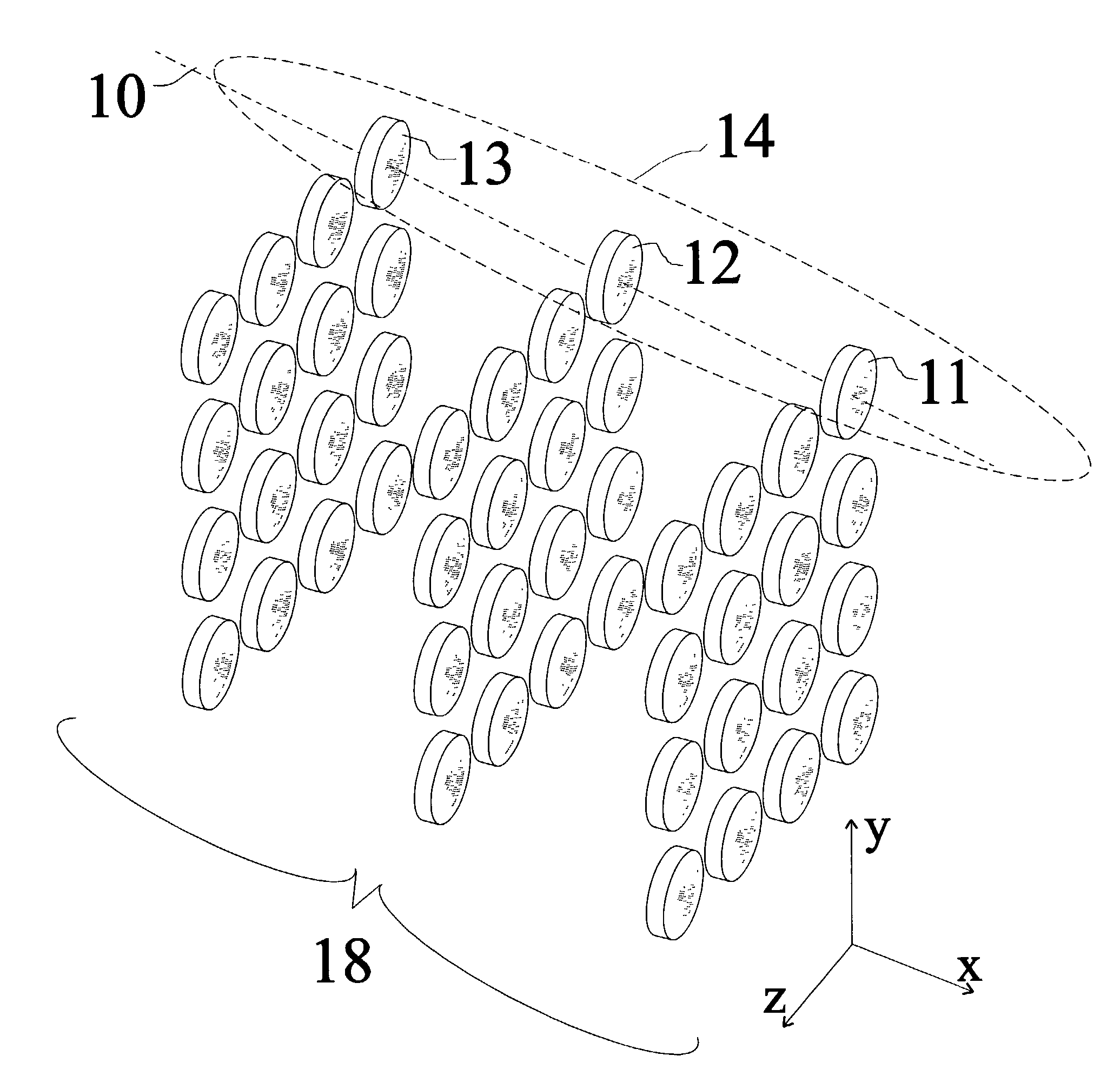
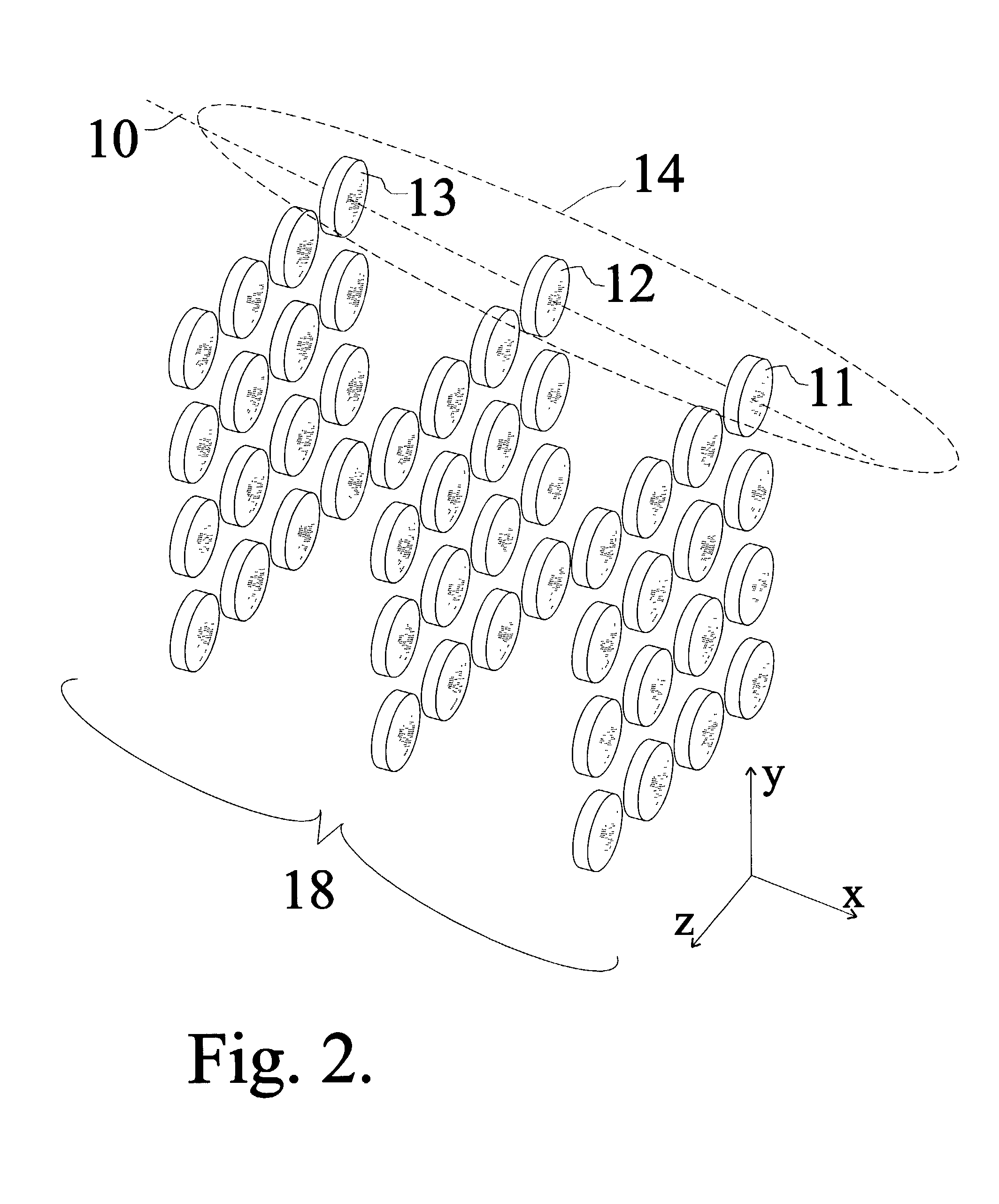
[0040]To increase the area of collection and imaging, 3-D arrays of unit lenses are used. FIG. 2 shows a partial solution and a fundamental component: the three dimensional (3-D) array of unit lenses. Arrays of concave unit lenses are aligned in rows and columns. The unit lenses 11, 12, and 13 are aligned so that the optical axis 10 of each is coaxial with succeeding unit convex lenses, forming a compound refractive lens 14. Identical compound refractive lenses are repeated in the y and z directions forming a 3-D lens array 18. Each compound refractive lens is capable of transporting x-rays or neutrons for collection, collimation, or imaging. The total number of unit lenses Nt is given by product of Nx, Ny and Nz, where Nx is the number of unit lenses in the x-direction, Ny is the number in y-direction, and Nz is the number in the z direction. Thus, Nt=NxNyNz.

[0041]A single 3-D array can be used for collection of x-ray or neutrons. Such an array ...


PUM


Abstract

An x-ray or neutron apparatus for the transmission of x-ray or neutron images is described, which includes x-ray- or neutron-three-dimensional (3-D) arrays or mosaics, including a plurality of x-ray or neutron lenses positioned so that they form a two-dimensional (2-D) mosaic of compound refractive lenses to provide a plurality of separate x-ray or neutron paths between an object and an image at an x-ray- or neutron-detector. The apparatus is so constructed that it permits separate parts of an object to be imaged such that a total composite image is formed from these various parts. An imaging apparatus of the detection of carcinoma in breast tissue is formed using such an apparatus. Methods of microscopy and imaging are obtained using this apparatus.

Description

CROSS REFERENCE TO RELATED APPLICATIONSU.S. Provisional Patent Documents[0001]Nos. 60 / 322,795 Sep. 17, 2001, M. A. Piestrup, “X-ray and neutron imaging using compound refractive lens arrays.”[0002]60 / 376,677 Apr. 29, 2002, M. A. Piestrup, “X-ray and neutron imaging using compound refractive lens arrays II.”CROSS REFERENCE TO RELATED DOCUMENTSU.S. Patent Documents[0003]U.S. Pat. No. 6,269,145 B1 May 1998, M. A. Piestrup, R. H. Pantell, J. T. Cremer and H. R. Beguiristain, “Compound Refractive Lens for X-rays,” issued: Jul. 31, 2001.[0004]U.S. Pat. No. RE28,162, R. H. Anderson, “Optical apparatus including a pair of mosaics of optical imaging elements,” issued Sep. 17, 1974.[0005]U.S. Pat. No. 5,594,773, Toshihisa Tomie, “X-ray Lens” issued Jan. 14, 1997.[0006]U.S. Pat. No. 5,880,478, D. J. Bishop, L. Gammel, and I. P. M. Platzman, Compound Refractive Lenses for Low Energy Neutrons,” issued Mar. 9, 1999.[0007]U.S. Pat. No. 6,765,197, H. R. Beguiristain, M. A. Piestrup, R. H. Pantell, ...

Claims


Application Information

Patent Timeline
Patent Type & Authority Patents(United States)
IPC IPC(8): G21K1/06A61B6/00
CPCG21K1/065G21K1/06A61B6/502A61B6/4092
Inventor PIESTRUP, MELVIN A.
Owner ADELPHI TECH INC
Why Eureka
Try Eureka