Method and apparatus for monitoring the integrity of satellite tracking data used by a remote receiver

a remote receiver and satellite tracking technology, applied in the field of satellite position location systems, can solve the problems of large position errors, large range errors of up to 0.8 m, and similar sized errors in the position of the gps receiver

a remote receiver and satellite tracking technology, applied in the field of satellite position location systems, can solve the problems of large position errors, large range errors of up to 0.8 m, and similar sized errors in the position of the gps receiver

US6992617B2Inactive Publication Date: 2006-01-31AVAGO TECH INT SALES PTE LTD

Image

  • Method and apparatus for monitoring the integrity of satellite tracking data used by a remote receiver
  • Method and apparatus for monitoring the integrity of satellite tracking data used by a remote receiver
  • Method and apparatus for monitoring the integrity of satellite tracking data used by a remote receiver

Examples


Embodiment Construction

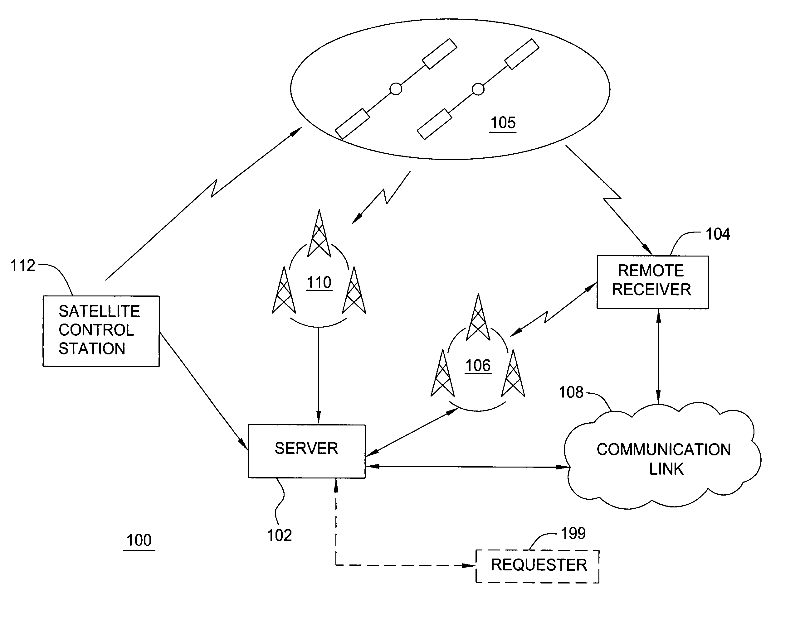
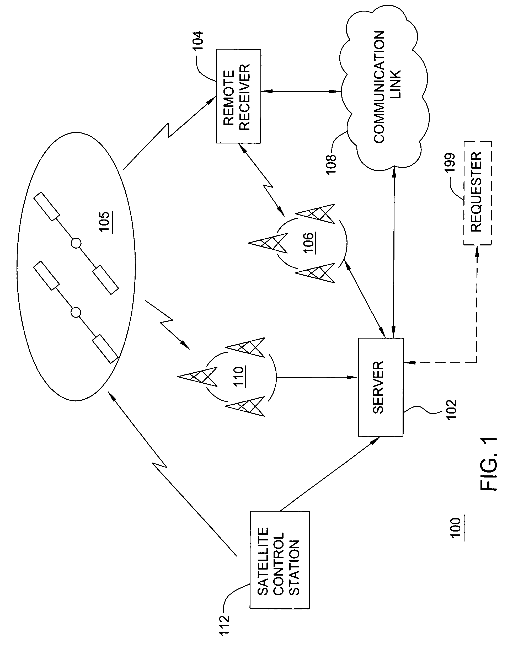
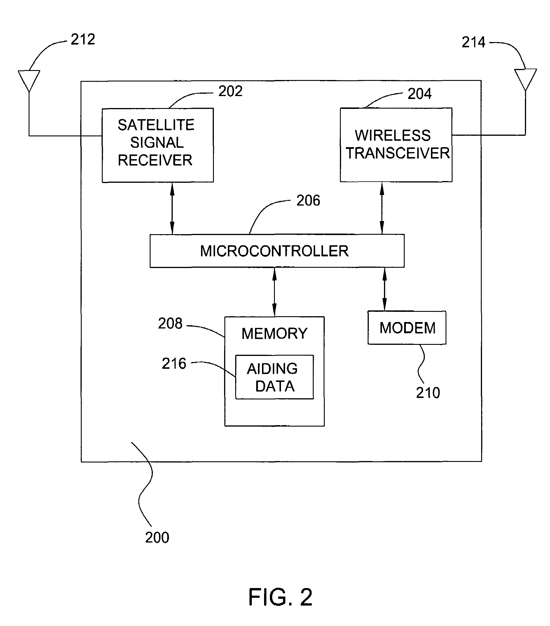
[0023]FIG. 1 is a block diagram depicting an exemplary embodiment of a position location system 100. The system 100 comprises a server 102 and a remote receiver 104. For purposes of clarity by example, the system 100 is shown with only a single remote receiver 104. It is to be understood, however, that the server 102 may be in communication with one or more remote receivers. The remote receiver 104 may be in communication with the server 102 via a wireless communication system 106 (e.g., cellular telephone network) or other type of communication link 108, such as the Internet, or both. The remote receiver 104 acquires satellite signals broadcast by a plurality of satellites 105 in a constellation and measures pseudoranges to the satellites 105 in order to locate its unknown position. For example, the remote receiver 104 may measure pseudoranges to a plurality of GPS satellites in the GPS constellation. To assist in the acquisition of satellite signals, the computation of position, o...


PUM


Abstract

A method and apparatus for monitoring the integrity of satellite tracking data used by a remote receiver is described. In one example, a first set of satellite tracking data is received at a server. Integrity data for a second set of satellite tracking data is generated using the first set of satellite tracking data. The integrity data is then transmitted to at least one remote receiver having the second set of satellite tracking data.

Description

BACKGROUND OF THE INVENTION[0001]1. Field of the Invention[0002]The present invention generally relates to satellite position location systems and, more particularly, to monitoring the integrity of satellite tracking data used by a remote receiver.[0003]2. Description of the Related Art[0004]Global Positioning System (GPS) receivers use measurements from several satellites to compute position. GPS receivers normally determine their position by computing time delays between transmission and reception of signals transmitted from satellites and received by the receiver on or near the surface of the earth. The time delays multiplied by the speed of light provide the distance from the receiver to each of the satellites that are in view of the receiver. The GPS satellites transmit to the receivers satellite-positioning data, so called ā€œephemerisā€ data. In addition to the ephemeris data, the satellites transmit to the receiver absolute time information associated with the satellite signal,...

Claims


Application Information

Patent Timeline
31 Jan 2006
Publication
US6992617B2
IPC
G01S5/02; H04B7/185; G01S19/05; G01S1/00
CPC
G01S19/05; G01S19/08; G01S19/20; G01S19/254; G01S19/258
Inventors
DIGGELEN, FRANK VAN; LUNDGREN, DAVID