Downlink beam hopping waveform

Active Publication Date: 2006-01-31
NORTHROP GRUMMAN SYST CORP
View PDF10 Cites 57 Cited by
  • Summary
  • Abstract
  • Description
  • Claims
  • Application Information

AI Technical Summary

Benefits of technology

[0009]A preferred embodiment of the present invention provides a downlink waveform for communicating payloads of data in a time division multiplexed frame stream. The frame signal includes a first payload field and a first header field with a first frame type indicator. The frame signal also includes a second payload field and a second h

Problems solved by technology

However, any transmission of overhead information necessarily reduces useful data throughput.
Such repetition is particularly undesirable in satellite communications, where bandwidth is extremely valuable and useful data throughput is critical to profitability.
In addition to reducing the useful information throughput, the duration of the overhead information represents a hand limit on the minimum delay between delivery of payload sections.
In other words, delivery of data that must be split across payload sections in multiple frames incurs an additional delivery delay for every frame.
Thus, large message

Method used


Image

  • Downlink beam hopping waveform
  • Downlink beam hopping waveform
  • Downlink beam hopping waveform

Examples


Example

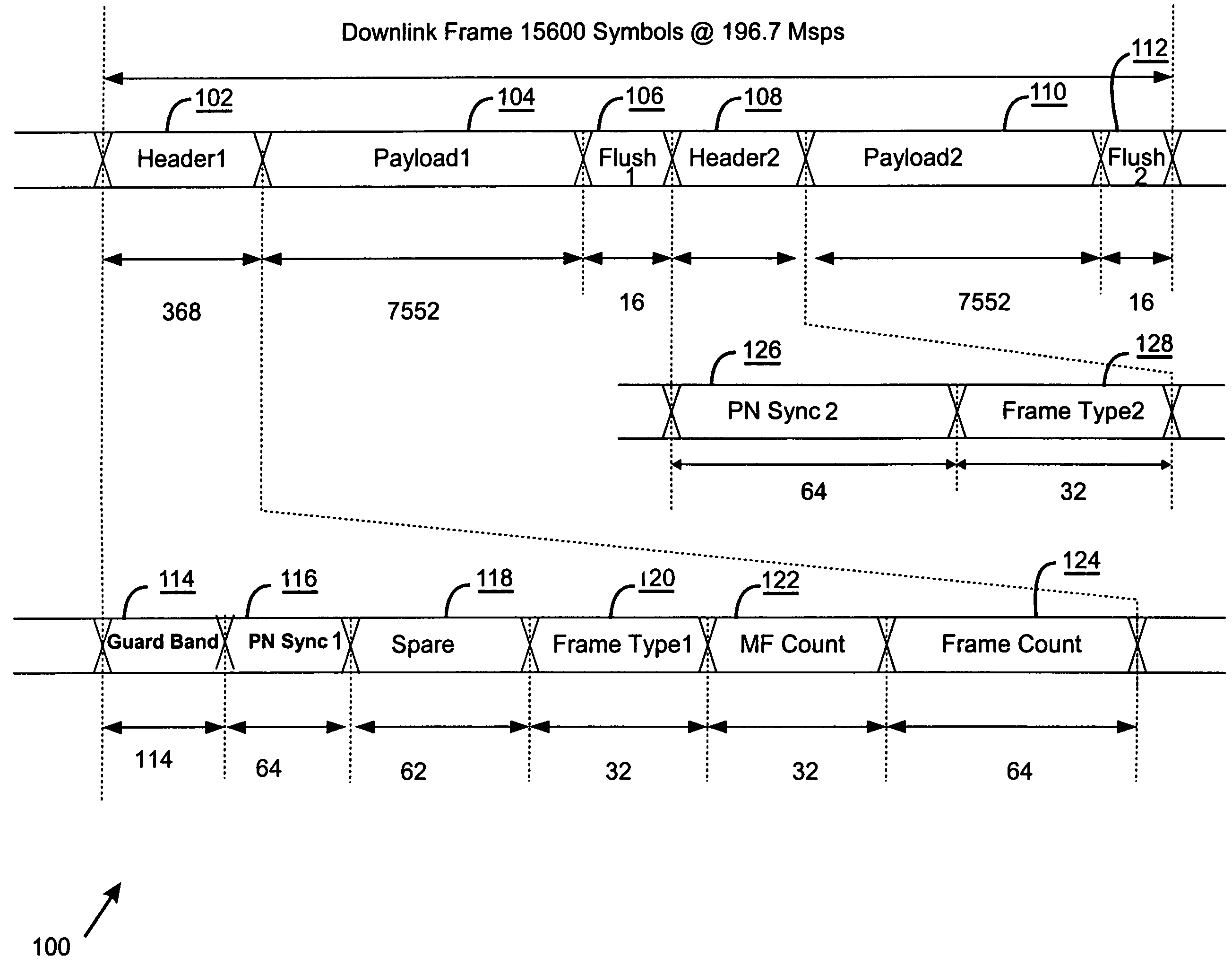
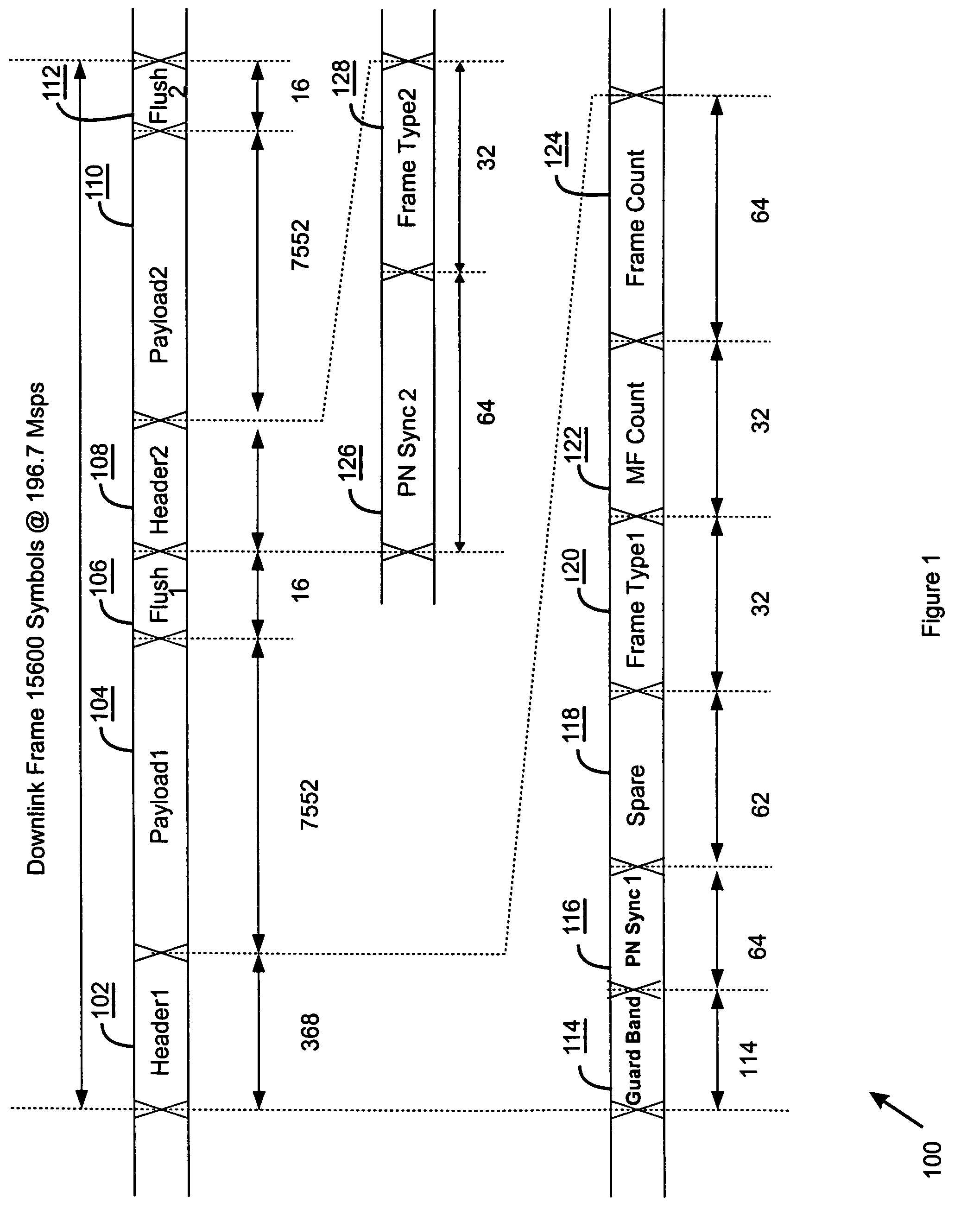
[0021]Turning now to FIG. 1, that figure illustrates a multiple payload frame signal 100. The frame 100 includes a first header field 102 followed by a first payload field 104 and a first flush field 106. In addition, the frame format 100 includes a second header field 108 followed by a second payload field 110 and another flush field 112. The first header field 102, first payload field 104, first flush field 106, second header field 108, second payload field 110, and second flush field 112 are all encapsulated into the single frame 100.

[0022]Continuing with reference to FIG. 1, the first header field 102 is composed of several subfields. In particular, the first header field 102 includes a hopping beam guard band 114, a first payload pseudorandom noise (PN) synchronization field 116, and a spare field 118. The first header field 102 also includes a first frame type field 120, a masterframe count field 122, and a subframe count field 124.

[0023]The second header section includes a sm...


PUM


Abstract

A frame signal (100) for communicating payloads (104, 110) of data includes a first payload field (104) and a first header field (102) with a first frame type indicator (120). The frame signal (100) also includes a second payload field (110) and a second header field (108) smaller than the first header field (102) that includes a second frame type indicator (128). The first payload field (104), first header field (102), second payload field (110), and the second header field (108) are encapsulated in a single frame (100) to provide multiple payload delivery with reduced overhead compared to individually transmitted single payload frames.

Description

CROSS-REFERENCE TO RELATED APPLICATIONS[0001]This application is related to TRW Docket No. 22-0067, titled “Downlink Transmission and Reception Techniques for a Processing Communication Satellite” filed Sep. 29, 1999 as application No. 09 / 408,041, by inventors David A. Wright et al., and since issued as U.S. Pat No. 6,512,749 B1.BACKGROUND OF THE INVENTION[0002]The present invention relates to satellite communication system downlink waveform structures. In particular, the present invention relates to an efficient satellite downlink waveform including multiple payloads per downlink frame which may be implemented using a hopping beam.[0003]Satellites produce spot beam downlinks that communicate information in time division multiplexed (TDM) frames. In general, the frames include an overhead section and a payload section. The overhead section includes, for example, a guard band and synchronization bits while the payload section carries the “billable” or “useful” data bits. Every time t...

Claims


Application Information

Patent Timeline
IPC IPC(8): H04B7/212H04L27/18H04B7/185H04J3/00H04L1/00H04L7/00
CPCH04B7/18513
Inventor COOPER, SCOTT A.JUE, REGINALDYOUSEFI, ESMAELLWRIGHT, DAVID A.LINSKY, STUART T.BEVER, MARK E.
Owner NORTHROP GRUMMAN SYST CORP
Why Eureka
Try Eureka