
Apparatus and method of OFDM demodulation

a technology of demodulation and apparatus, applied in the direction of frequency-division multiplex, orthogonal multiplex, synchronisation signal speed/phase control, etc., can solve the problems of interference between symbols, interference between symbols, and difficulty in establishing synchronization of frequency and symbol of ofdm signal in the receiver, so as to achieve the effect of minimizing adjacent symbol interferen

Inactive Publication Date: 2006-01-31
INTERDIGITAL PATENT HLDG INC
View PDF13 Cites 73 Cited by
  • Summary
  • Abstract
  • Description
  • Claims
  • Application Information

AI Technical Summary

Benefits of technology

[0014]Therefore, a first object of the present invention is to provide an apparatus for OFDM demodulation capable of setting symbol timing in such a manner as to minimize adjacent-symbol interference even if a transmission path characteristic varies with time, and a method therefor.
[0016]A third object of the present invention is to provide an apparatus for OFDM demodulation, if a sampling frequency shift is observed, correcting the symbol timing so as not to cause a shift among valid symbol periods by the location of transmission symbols in a transmission frame, and a method therefor.
[0053]As described above, in the third aspect, in addition to the control in the first aspect, frequency error correction is carried out in the first frequency corrector before calculating a correlation between the OFDM signal and the synchronous symbol signal. In this manner, accuracy in detecting the synchronous symbol can be further improved. This is because a frequency-corrected signal is used for symbol synchronization and further frequency correction for the second time.
[0070]As described above, in the fourth to fifteenth aspects, the timing of the valid symbol period is controlled for Fourier transform to be so carried out as to minimize the between-symbol interference. This is done by first calculating a correlation between the OFDM signal and the prestored synchronous symbol signal, secondly integrating the correlation by a predetermined integral section width, and lastly, based on the integrated correlation obtained thereby, detecting the synchronous symbol. In this manner, the OFDM signal can be demodulated, i.e., the transmission data can be reproduced with the between-symbol interference minimized even if a transmission path characteristic varies with time.
[0091]As described above, in the eighteenth aspect, a phase change is estimated from the phase shift occurred in the symbols, and then the information about the transmission path characteristic is corrected based thereon. Accordingly, it is possible to correct a shift, due to the sampling frequency shift, between window timing at the time of Fourier transform for a reference symbol used to estimate the information about the transmission path characteristic and window timing at the time of Fourier transform for the OFDM signal before equalization. In this manner, accuracy in equalizing the signal is improved.

Problems solved by technology

The above-described OFDM signal may take such waveform as random noise, therefore it is difficult to establish synchronization in frequency and symbol of the OFDM signal in the receiver.
In the case that the OFDM signal is demodulated without frequency synchronization, the orthogonality relation among the subcarriers is lost and thus interference occurs.
Further, if the receiver cannot establish symbol synchronization, that is, when the receiver cannot correctly extract the valid symbol from the transmission symbol, interference occurs between the symbols.
Accordingly in either case, the receiver fails to correctly reproduce the transmission data.
However, this is not applicable to a case where the delay of the delay wave is beyond the guard interval.
It may result in extracting the valid symbol having been influenced by the adjacent-symbol interference (FIG.
Consequently, when the delay of the delay wave is beyond the guard interval, the conventional receiver is incapable of setting the symbol timing in such a manner as to minimize the adjacent-symbol interference.
Consequently, the conventional receiver cannot satisfactorily detect the synchronous symbol therein.
If this is the case, the symbol timing setting based on detection of the synchronous symbol as the conventional receiver is not sufficient.

Method used


Image

  • Apparatus and method of OFDM demodulation
  • Apparatus and method of OFDM demodulation
  • Apparatus and method of OFDM demodulation

Examples


first embodiment

[0187](First Embodiment)

[0188]By referring to FIGS. 1 to 7, an apparatus and a method for OFDM demodulation are described according to a first embodiment of the present invention.

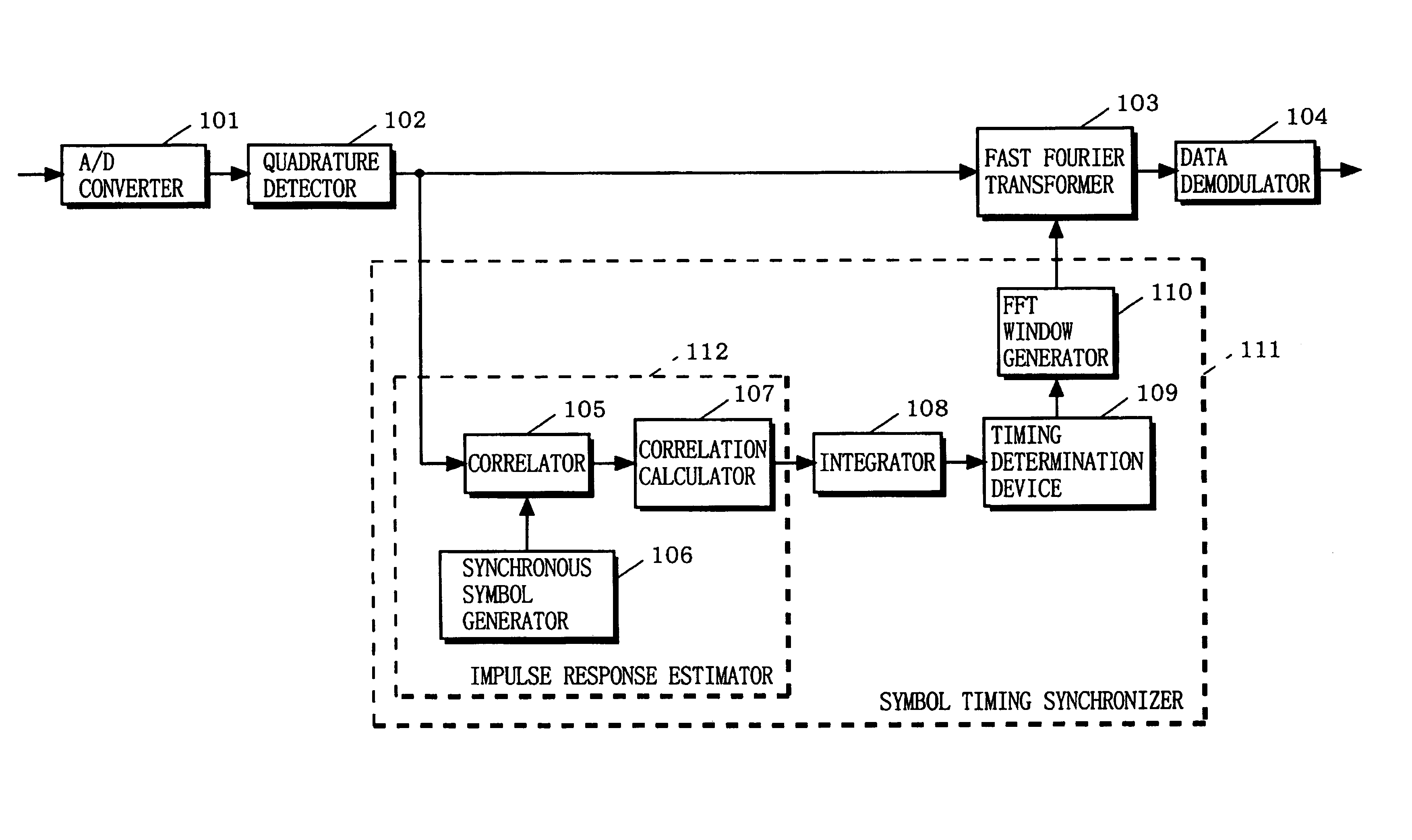
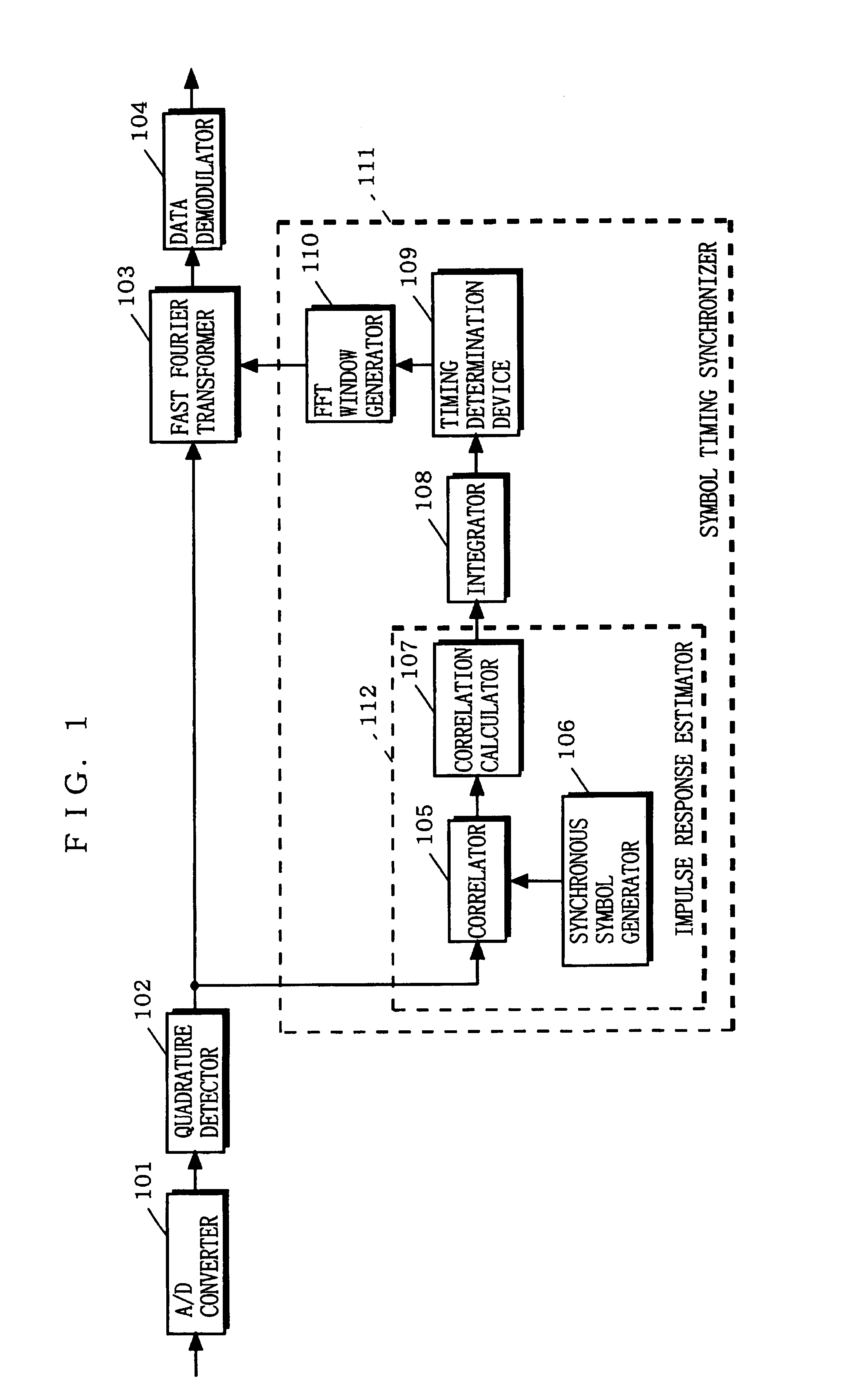
[0189]FIG. 1 is a block diagram showing the structure of the apparatus for OFDM demodulation of the first embodiment. In FIG. 1, the apparatus is provided with an A / D converter 101, an quadrature detector 102, a fast Fourier transformer 103, a data demodulator 104, and a symbol timing synchronizer 111. The symbol timing synchronizer 111 includes an impulse response estimator 112, an integrator 108, a timing determination device 109, and an FFT window generator 110. The impulse response estimator 112 includes a correlator 105, a synchronous symbol generator 106, and a correlation calculator 107.

[0190]First, it is described how the apparatus for OFDM demodulation of the first embodiment operates on a constituent basis.

[0191]An OFDM signal transmitted from a transmitter (not shown) is received by a tuner (not ...

second embodiment

[0212](Second Embodiment)

[0213]By referring to FIG. 8, an apparatus and a method for OFDM demodulation are described according to a second embodiment of the present invention.

[0214]FIG. 8 is a block diagram showing the structure of an apparatus for OFDM demodulation of the second embodiment. In FIG. 8, the apparatus is provided with the A / D converter 101, the quadrature detector 102, the fast Fourier transformer 103, the data demodulator 104, the symbol timing synchronizer 111, and a first frequency synchronizer 207. The first frequency synchronizer 207 includes a delay device 201, a multiplier 202, an averaging device 203, a frequency error calculator 204, a holder 205, and a frequency corrector 206.

[0215]As shown in FIG. 8, the apparatus for OFDM demodulation of the second embodiment is additionally provided with the first frequency synchronizer 207 compared with the apparatus of the first embodiment. The first frequency synchronizer 207 estimates and corrects a frequency shift am...

third embodiment

[0222](Third Embodiment)

[0223]By referring to FIGS. 9 and 10, an apparatus and a method for OFDM demodulation are described according to a third embodiment of the present invention.

[0224]FIG. 9 is a block diagram showing the structure of the apparatus for OFDM demodulation of the third embodiment. In FIG. 9, the apparatus is provided with the A / D converter 101, the quadrature detector 102, the fast Fourier transformer 103, the data demodulator 104, the symbol timing synchronizer 111, the first frequency synchronizer 207, and a second frequency synchronizer 310. The second frequency synchronizer 310 includes a delay device 301, a multiplier 302, an averaging device 303, a frequency error calculator 304, a holder 305, a filter 306, an absolute value calculator 307, a timing determination device 308, and a frequency corrector 309.

[0225]As shown in FIG. 9, the apparatus for OFDM demodulation of the third embodiment is additionally provided with the second frequency synchronizer 310 comp...


PUM


Abstract

An apparatus and method for OFDM demodulation establish symbol synchronization to minimize between-symbol interference even under an environment where multipath occurs.An incoming signal is an OFDM signal including a transmission symbol structured by a valid symbol period and a guard interval, and a predetermined synchronization symbol is included in the OFDM signal for every transmission frame. A correlator calculates how a signal generated by a synchronization symbol generator and the OFDM signal are correlated. A correlation calculator then calculates a correlation therefrom. An integrator integrates the calculated correlation by the guard interval. A timing determination device determines symbol timing from the integrated correlation. An FFT window generator outputs operation timing for Fourier transform from the determined symbol timing. Based on the signal outputted from the FFT window generator, the apparatus for OFDM demodulation extracts a signal in the valid symbol period from the transmission symbol for demodulation.

Description

BACKGROUND OF THE INVENTION[0001]1. Field of the Invention[0002]The present invention relates to apparatuses and methods for OFDM demodulation, and more particularly to an apparatus and a method for demodulating a signal transmitted under an orthogonal frequency division multiplex (OFDM) technique.[0003]2. Description of the Background Art[0004]In recent years, a transmission mode applying the OFDM technique has been popular for digital terrestrial television broadcasting, mobile communications, and the like. The OFDM mode is included in a multicarrier modulation scheme, and carries out OFDM signal transmission from a transmitter to a receiver. The transmitter assigns transmission data to a large number of subcarriers having an orthogonality relation between any adjoining two, and the subcarriers are each modulated by the transmission data assigned thereto. Thereafter, the transmitter collectively subjects the modulated subcarriers to inverse Fourier transform to generate an OFDM si...

Claims


Application Information

Patent Timeline
Patent Type & Authority Patents(United States)
IPC IPC(8): H04L7/04H04L27/26
CPCH04L27/2665H04L27/2662
Inventor SHIRAKATA, NAGANORIKIMURA, TOMOHIROTANAKA, KOICHIRONAKAHARA, HIDEKIHARADA, YASUOHOSOKAWA, SHUYA
Owner INTERDIGITAL PATENT HLDG INC
Learn More