Coarse frequency synchronisation in multicarrier systems

a multi-carrier system and coarse frequency synchronisation technology, applied in the field of coarse frequency synchronization in multi-carrier systems, can solve the problems of inapplicability to transmission over multi-path fading channels with large frequency offsets or mcm transmission systems, without major changes, and the methods for frame synchronization available up to date require either prior achieved frequency synchronization or become very complex

Inactive Publication Date: 2006-01-31
FRAUNHOFER GESELLSCHAFT ZUR FOERDERUNG DER ANGEWANDTEN FORSCHUNG EV
View PDF25 Cites 43 Cited by
  • Summary
  • Abstract
  • Description
  • Claims
  • Application Information

AI Technical Summary

Benefits of technology

[0077]Synchronization to the reference symbol, i.e. the frame header is the first step to initiate radio reception. The reference symbol is structured to accomplish this. The information contained in the reference symbol must therefore be independent of other synchronization parameters, e.g. frequency offset. For this reason, in accordance with the present invention, the form of the reference symbol selected is an amplitude modulated sequence (AM sequence) in the complex baseband. Thus, the information contained in the reference symbol is only that given in the amplitude and not that in the phase. Note that the phase information will be corrupted by a possible frequency offset. In preferred embodiments of the present invention, the AM information is constructed from a bit sequence with special features. The information sequence is selected in a way which makes it easy and secure to find it in the time domain. A bit sequence with good autocorrelation properties is chosen. Good autocorrelation properties means a distinct correlation maximum in a correlation signal which should be as white as possible.
[0079]Using the envelope of the signal to carry bit information offers additional flexibility. First it has to be decided which envelope values should correspond to the binary values of 0 and 1. The parameters are mean amplitude and modulation rate. Attention should be paid to selecting the mean amplitude of the reference symbol (performance) identically to the mean amplitude of the rest of the frame. This is due to the amplitude normalization (AGC; AGC=Automatic Gain Control) performed in the receiver. It is also possible to select the mean amplitude of the reference symbol higher than the mean signal amplitude, but then care has to be taken that the time constant of the AGC (1 / sensitivity) is selected high enough to secure that the strong (boosted) signal of the reference symbol does not influence the AGC control signal and thus attenuate the signal following the reference symbol.
[0083]With increasing m the modulating signal mod(t) is expanded in time relative to the basic binary sequence, this results in a bandwidth compression of the resulting AM spectrum with regard to the basic binary sequence. A time expansion by a factor 2 results in a bandwidth compression by the same factor 2. In addition to the bandwidth compression, a further advantage of a higher modulation degree d is a reduced complexity of the search method in the receiver due to the fact that only each dth sample has a corresponding binary value. Choosing the factor d=1 is not preferred since this would result in aliasing due to disregard of the sampling theorem. For this reason, in a preferred embodiment of the present invention d is chosen to be 2.
[0086]Thus, the present invention shows how to find a reference symbol by a detection method which is simple. Furthermore, the present invention can be used for one-carrier or multi-carrier systems. The present invention is particularly useful in multi-carrier modulation systems using an orthogonal frequency division multiplexing, for example in the field of digital broadcasting. The synchronization methods according to the present invention are independent of other synchronization steps. Since the information needed for the synchronization is contained in the envelope of the preamble, i.e. the reference symbol, the reference symbol is independent of possible frequency offsets. Thus, a derivation of the correct down sampling timing and the correct positioning of the FFT window can be achieved. The reference symbol of the present invention can be detected even if the frequency synchronization loop is not yet locked or even in the case of a carrier frequency offset. The frame synchronization method in accordance with the present invention is preferably performed prior to other and without knowledge of other synchronization efforts.

Problems solved by technology

These prior art methods based on correlation are, without major changes, not applicable for transmission over multipath fading channels with large frequency offsets or MCM transmission systems that use, for example, an orthogonal frequency division multiplexing.
In the presence of large frequency offsets, this algorithm becomes very complex because several correlators must be implemented in parallel.
The methods for frame synchronization available up to date require either prior achieved frequency synchronization or become very complex when the signal in the receiver is corrupted by a large frequency offset.
If there is a frequency offset in the receiver, as can easily be the case when a receiver is powered-on and the frequency synchronization loop is not yet locked, problems will occur.
In general, frequency offset increases implementation complexity.
A deviation of this magnitude puts high demands on the above methods.
In multipath channels, frame synchronization methods with correlations can not be used without major changes.
Moreover, it is not possible to use data demodulated from the MCM system, because the demodulation is based on the knowledge of the position of the guard interval and the useful part of the MCM symbol.

Method used


Image

  • Coarse frequency synchronisation in multicarrier systems
  • Coarse frequency synchronisation in multicarrier systems
  • Coarse frequency synchronisation in multicarrier systems

Examples


Embodiment Construction

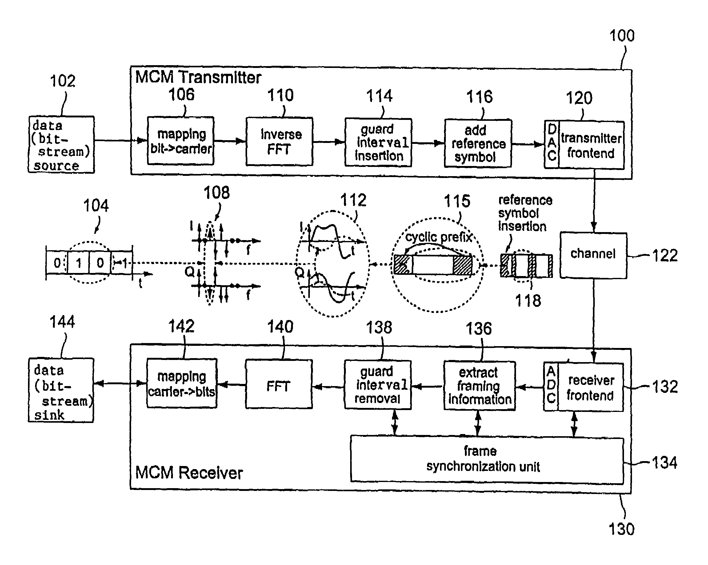
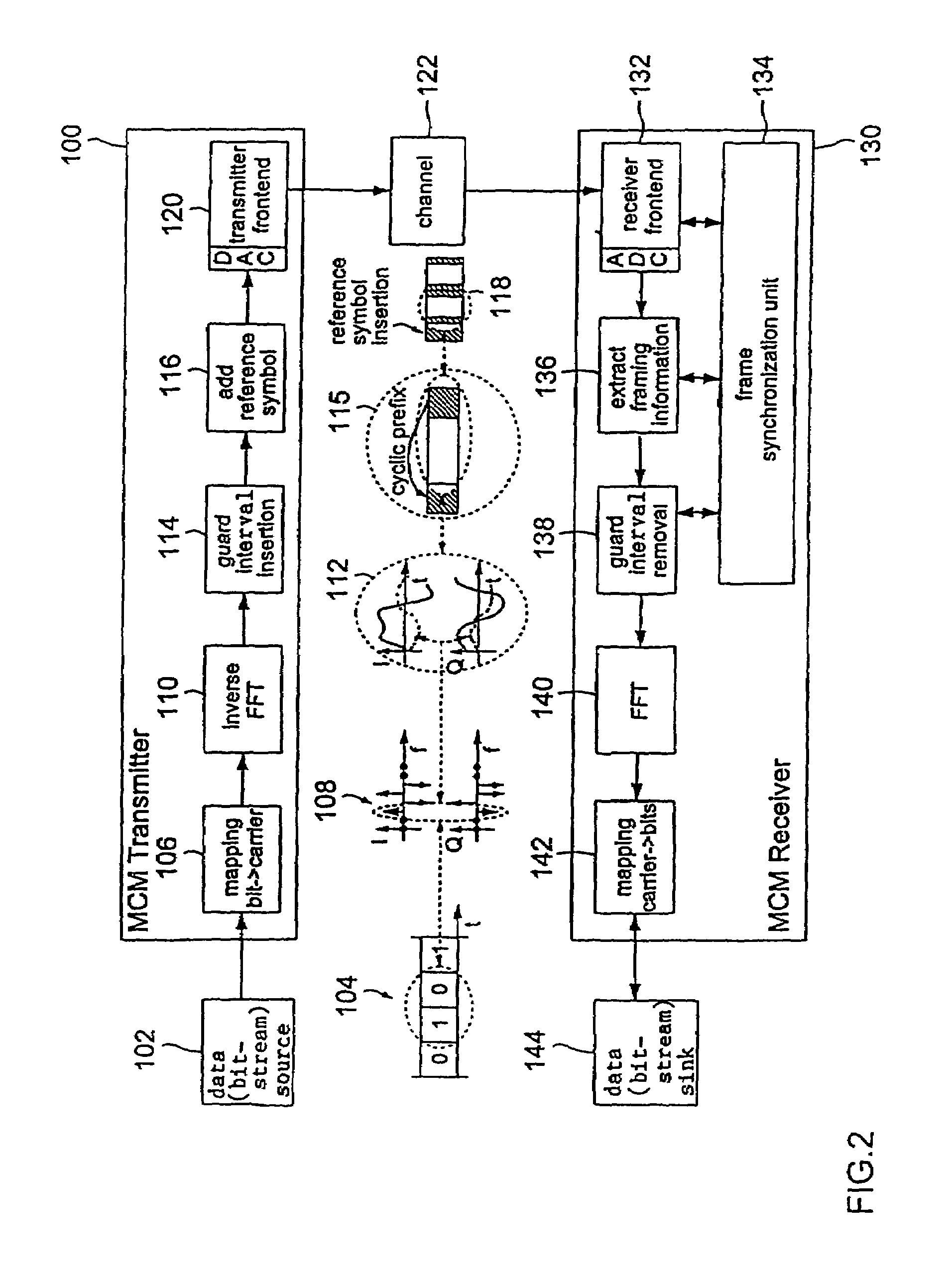
[0093]Although the present invention is explained mainly referring to a MCM system, it is obvious that the present invention can be used in connection with different signal transmissions that are based on different kinds of modulation.

[0094]FIG. 2 shows a MCM system overview on the basis of which the present invention will be described in detail. At 100 a MCM transmitter is shown that substantially corresponds to a prior art MCM transmitter except for the kind of the reference symbol being added to each frame of a MCM signal. A description of such a MCM transmitter can be found, for example, in William Y. Zou, Yiyan Wu, “COFDM: AN OVERVIEW”, IEEE Transactions on Broadcasting, vol. 41, No. 1, March 1995.

[0095]A data source 102 provides a serial bitstream 104 to the MCM transmitter. The incoming serial bitstream 104 is applied to a bit-carrier mapper 106 which produces a sequence of spectra 108 from the incoming serial bitstream 104. An inverse fast Fourier transform (FFT) 110 is perf...


PUM


Abstract

A method for generating a signal having a frame structure, each frame of the frame structure comprising at least one useful symbol, a guard interval associated to the at least one useful symbol and a reference symbol, comprises the steps of performing an amplitude modulation of a bit sequence such that the envelope of the amplitude modulated bit sequence defines a reference pattern of the reference symbol and inserting the amplitude modulated bit sequence into said signal as said reference symbol. A method for frame synchronization of a signal having such a frame structure comprises the steps of receiving the signal, down-converting the received signal, performing an amplitude-demodulation of the down-converted signal in order to generate an envelope, correlating the envelope with a predetermined reference pattern in order to detect a signal reference pattern of the reference symbol in the signal, and performing the frame synchronization based on the detection of the signal reference pattern.

Description

FIELD OF THE INVENTION[0001]The present invention relates to methods and apparatus for generating a signal having a frame structure, wherein each frame of the frame structure is composed of useful symbols, a guard interval associated to each useful symbol and one reference symbol. In addition, the present invention relates to methods and apparatus for frame synchronization of signals having the above structure.[0002]The present invention is particularly useful in a MCM transmission system (MCM=Multi-carrier modulation) using an orthogonal frequency division multiplexing (OFDM) for digital broadcasting.BACKGROUND OF THE INVENTION[0003]In a MCM (OFDM) transmission system the binary information is represented in the form of a complex spectrum, i.e. a distinct number of complex subcarrier symbols in the frequency domain. In the modulator a bitstream is represented by a sequence of spectra. Using an inverse Fourier-transform (IFFT) a MCM time domain signal is produced from this sequence ...

Claims


Application Information

Patent Timeline
Patent Type & Authority Patents(United States)
IPC IPC(8): H04L27/28H04J11/00H04J1/00H04L27/26
CPCH04L5/0048H04L27/2605H04L27/2675H04L27/2656H04L27/2657H04L27/2613H04L27/26
Inventor EBERLEIN, ERNSTBADRI, SABAHLIPP, STEFANBUCHHOLZ, STEPHANHEUBERGER, ALBERTGERHAEUSER, HEINZ
Owner FRAUNHOFER GESELLSCHAFT ZUR FOERDERUNG DER ANGEWANDTEN FORSCHUNG EV
Why Eureka
Try Eureka