
Device for performing and verifying a therapeutic treatment and corresponding computer program and control method

Inactive Publication Date: 2006-01-31
DEUTES KREBSFORSCHUNGSZENT STIFTUNG DES OFFENTLICHEN RECHTS
View PDF11 Cites 114 Cited by
  • Summary
  • Abstract
  • Description
  • Claims
  • Application Information

AI Technical Summary

Benefits of technology

[0018]It is essential for the invention that these examinations and corrections are based on the three-dimensional information detected in the first step, thereby providing much more accuracy compared to purely two-dimensional comparison proposed by the above-mentioned prior art.
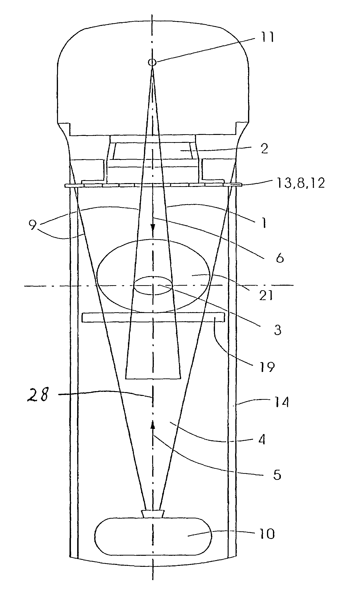
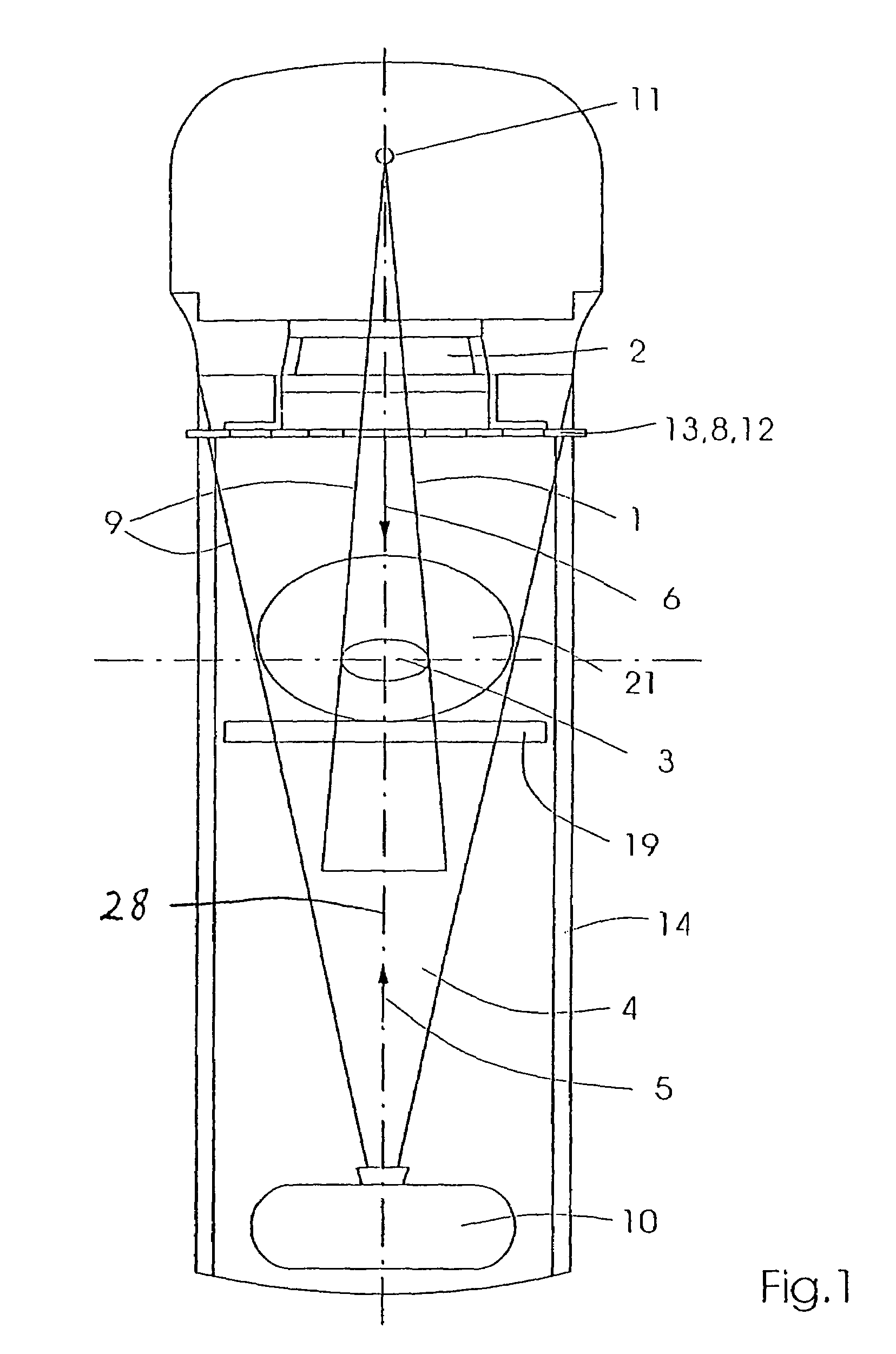
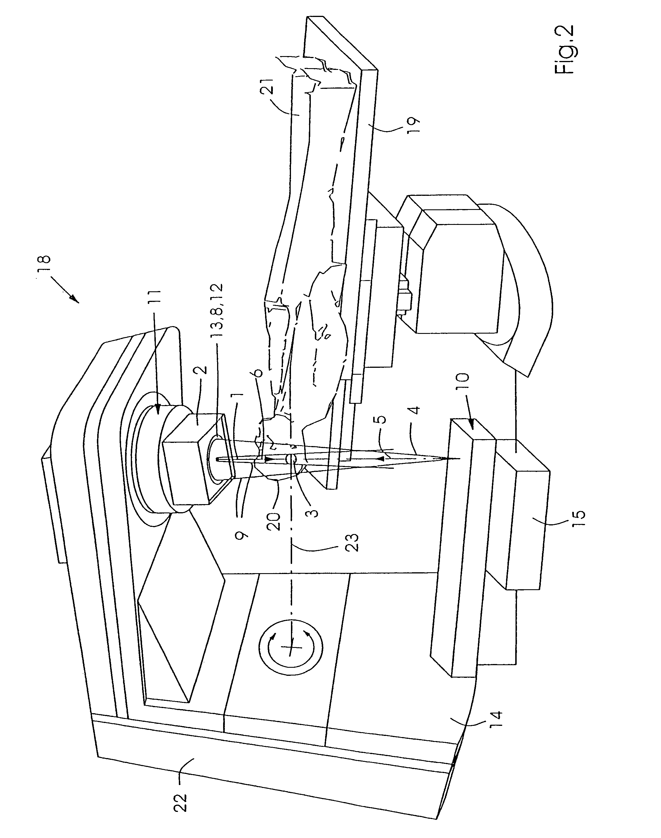
[0021]As mentioned above, it is of particular importance that the shape and position of endangered organs is taken into consideration for verification and correction of the modulation of the high-energy beam. The controller, the method and the computer program for carrying out the control must be designed accordingly. Towards this end, the invention provides particular advantages compared to conventional devices and methods, since spatial detection and verification considerably reduces the danger of substantial damage due to changes in position and anatomy. To be able to perform the above-mentioned verification in minimum time thereby taking into consideration a three-dimensional instantaneous recording, the X-ray beam can detect a partial region of the target volume including a bordering region of an endangered organ during the transmitting breaks in the high-energy beam, and this detection is taken into consideration for verification in real time. This limits the processed data to the critical region, considerably reducing its amount while still providing continuous exact examination in three-dimensional space where required.
[0024]In an advantageous further development of the device, both media for detecting the high-energy beam and for detecting the X-ray beam are designed as one common medium. In this manner, one detection medium is omitted and the overall number of devices is reduced. Association of the two detections is also simplified. The individual detection elements can thereby also be used for detecting both beams by e.g. detecting the X-ray beam directly on the surface and the therapeutic beam during penetration through the medium. The medium must consist of a material which is not damaged by the energetic therapeutic beam. The medium may e.g. be an array of photo diodes, which consist of an amorphous material, e.g. amorphous silicon or amorphous selenium. The beams cannot thereby destroy a lattice structure. The photo diodes should also be disposed in a housing which minimally attenuates the high-energy beam such that processing is not subject to differences which would be relevant to the treatment. The photo diodes could e.g. be disposed in a plastic housing which would prevent any noticeable weakening or scattering of radiation.

Problems solved by technology

This device only permits comparison of the outer contours of the therapeutic ray with the outer contours of the target volume.
Spatial detection, detection of the treatment intensity of regions to be irradiated with different intensities and detection of the anatomy of the irradiation surroundings are not possible.

Method used


Image

  • Device for performing and verifying a therapeutic treatment and corresponding computer program and control method
  • Device for performing and verifying a therapeutic treatment and corresponding computer program and control method
  • Device for performing and verifying a therapeutic treatment and corresponding computer program and control method

Examples


Embodiment Construction

[0029]FIG. 1 shows the principle of the invention using an embodiment of the inventive device. A high-energy beam 1 is generated by a radiation source 11 and modulated by a means for beam modulation 2, e.g. a multileaf collimator, in accordance with the treatment plan, and directed onto a target volume 3. This is generally a tumor of a patient 21 who is lying on a patient table 19. In accordance with the invention, a medium 8 for detecting the high-energy modulated beam 1 with respect to its shape and regions 16, 16′, 16″ of different radiation doses (FIG. 3) is disposed in the path of rays 9 between the means 2 for radiation modulation and the patient 21, such that the shaping and intensity modification of the device 2 for radiation modulation can be detected and monitored. If the modulation of the ray 1 differs from its desired value, switching off or correction-may follow.

[0030]A radiation source 10 for an X-ray beam 4 is disposed opposite to the radiation source 11 for the high-...


PUM


Abstract

The invention relates to a device for performing and verifying therapeutic radiation. An x-ray beam (4) is arranged across from a target volume (3) of the beam source (11) for the high-energy beam (1) in such a way that the beams (1, 4) run in essentially opposite directions (5, 6). The invention also relates to a computer program and a control method for operating said device. The inventive device makes it possible to exactly verify areas (16, 16′, 16″) that are subjected to different levels of radiation, the entire anatomy of the target volume (3), and the surroundings thereof in addition to the contour of the therapy beam (1). The x-ray beam (4) detects the anatomy and position of the patient (21) within the range of the target volume (3) before the high-energy beam (1) is applied and the shape of the applied high-energy beam (1) is then detected and areas (16, 16′, 16″) that are subjected to different levels of radiation as well as at least one partial segment of the target volume (3) during the emission breaks of the high-energy beam (1). The detected data is used for correcting the treatment plan.

Description

[0001]This application is the national stage of PCT / EP02 / 02693 filed on Mar. 12, 2002.BACKGROUND OF THE INVENTION[0002]The invention concerns a device for performing and verifying therapeutic radiation, comprising a radiation source for a high-energy beam and a means for modulation of the high-energy beam on the gantry of an irradiation device, wherein for verification, an X-ray beam is disposed across from a radiation source for high energy beams and opposite a target volume of the radiation source for those high-energy beams such that the rays extend substantially oppositely to each other, and with a medium for detecting the X-ray beam disposed, relative to its radiation direction, behind the target volume and a medium for detecting the high-energy beam disposed, relative to the direction of this ray, before the target volume. The invention also concerns a computer program and a control method for operating this device.[0003]A device of this type is disclosed in U.S. Pat. No. 5,23...

Claims


Application Information

Patent Timeline
IPC IPC(8): A61N5/10
CPCA61N5/1042A61N5/1049A61N2005/1054
Inventor HESSE, BERND-MICHAEL
Owner DEUTES KREBSFORSCHUNGSZENT STIFTUNG DES OFFENTLICHEN RECHTS
Learn More