
Cable data service method
a data service and cable technology, applied in the field of data service, can solve the problems of system signal-to-noise ratio (snr) demands, current systems might not be able to meet, etc., and achieve the effect of improving the peak ra
- Summary
- Abstract
- Description
- Claims
- Application Information
AI Technical Summary
Benefits of technology
Problems solved by technology
Method used
Image

Examples
Embodiment Construction
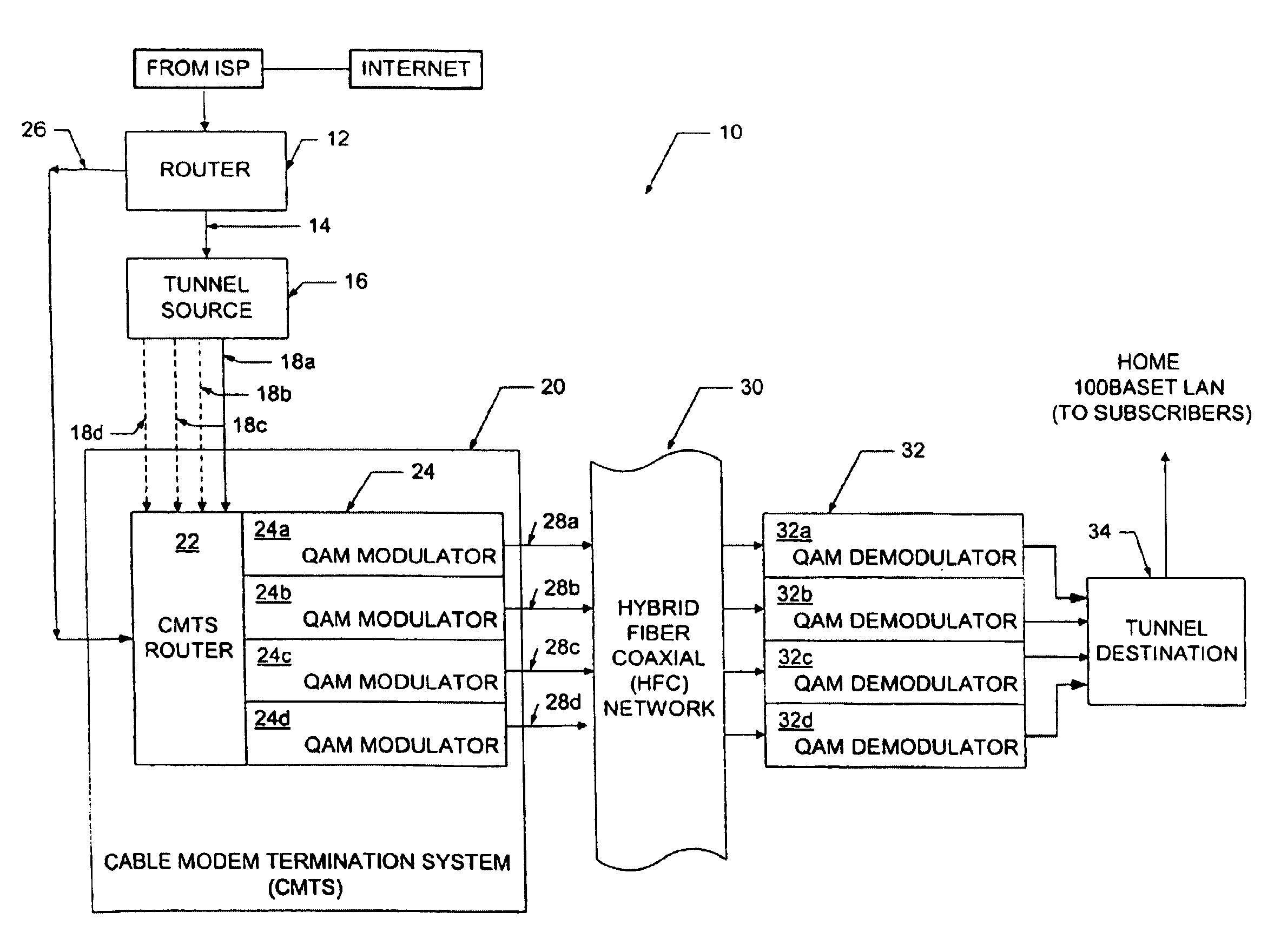
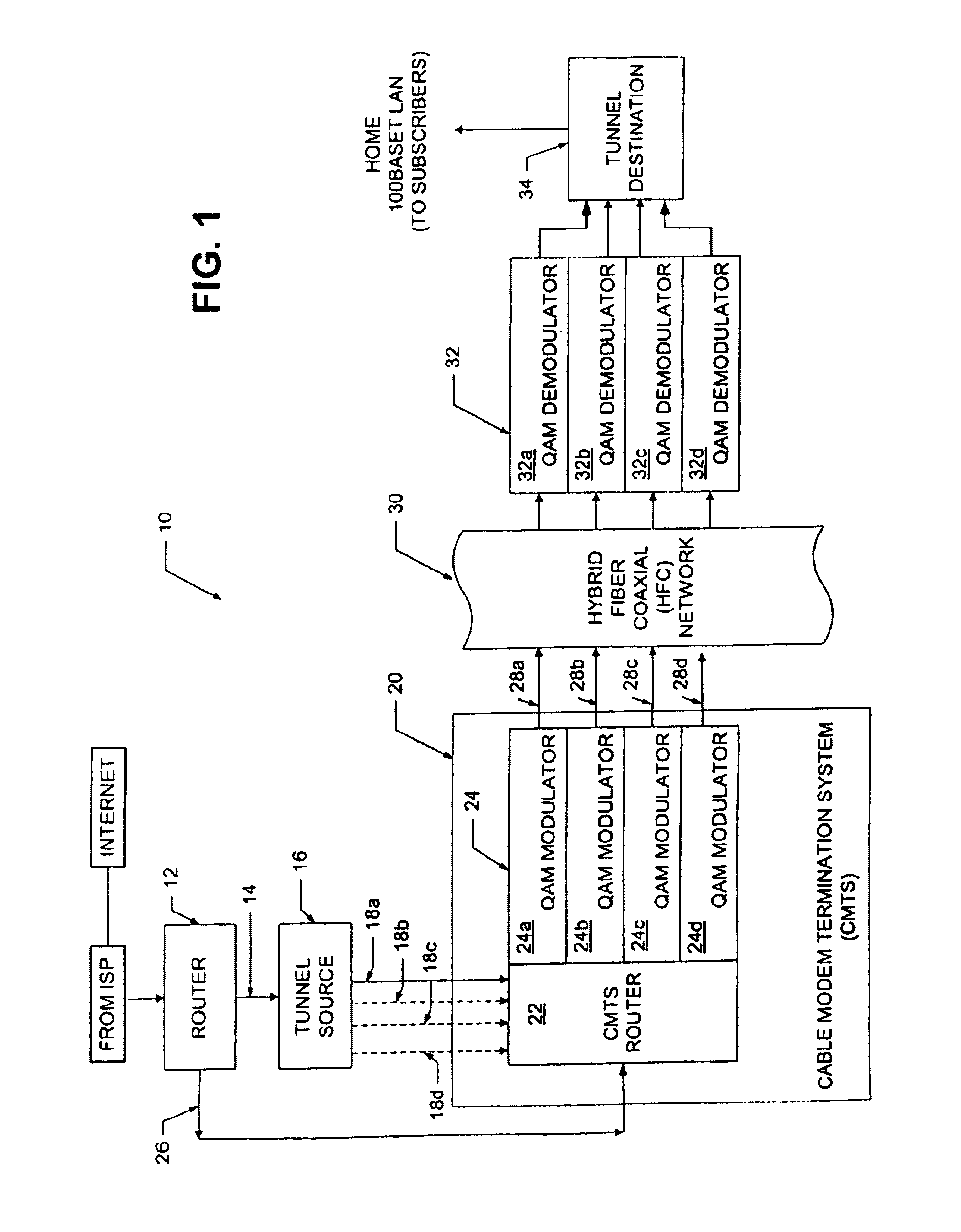
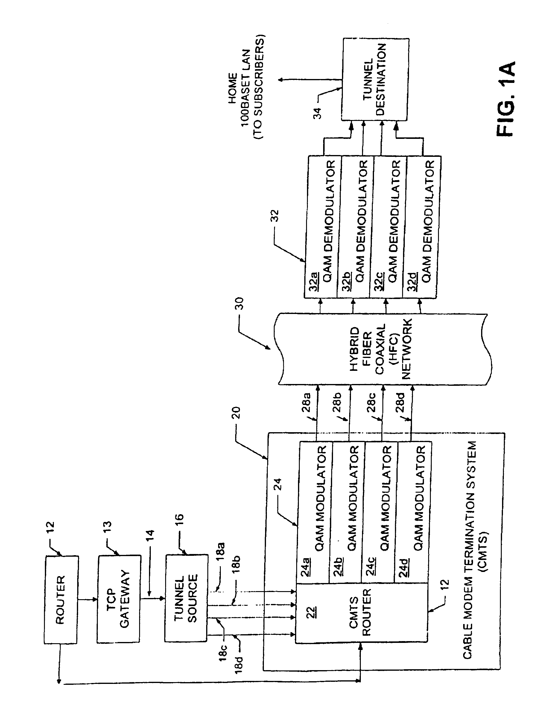
[0025]Referring now to FIG. 1, a downstream path of a transmission system 10 includes a first router 12 coupled to a tunnel source (also referred to as a sending tunnel end-point) 16 through a first signal path 14 (referred to hereinbelow as a FastChannel path). Tunnel source 16 is coupled to a cable modem termination system (CMTS) 20 through a second signal path 18 here shown as signal paths 18a–18d. It should be appreciated that the tunnel source 16 can functionally reside in a separate box upstream of the CMTS 20 as shown in FIG. 1. Alternatively, however, the tunnel source 16 can functionally reside within the CMTS 20 or the router 12.
[0026]The CMTS 20 includes a CMTS router 22 and a plurality of quadrature amplitude modulators (QAMs) 24a–24d generally denoted 24. Router 12 is also coupled to the CMTS 20, and in particular to the CMTS router 22, via a signal path 26. The purpose of the signal paths 14 and 26 will next be described in general overview.
[0027]In the system of the p...
PUM
 Abstract
Description
Claims
Application Information