
Telemetry duty cycle management system for an implantable medical device

Inactive Publication Date: 2006-01-31
CARDIAC PACEMAKERS INC
View PDF74 Cites 289 Cited by
  • Summary
  • Abstract
  • Description
  • Claims
  • Application Information

AI Technical Summary

Benefits of technology

[0005]The present invention includes a system and method for managing the duty cycles of RF telemetry components in an implantable medical device and an external device in order to lessen power consumption. In accordance with the invention, the RF telemetry circuitry of both devices is

Problems solved by technology

This requirement is inconvenient for the patient and the clinician, and thereby limits the situations in which telemetry can take place.

Method used


Image

  • Telemetry duty cycle management system for an implantable medical device
  • Telemetry duty cycle management system for an implantable medical device
  • Telemetry duty cycle management system for an implantable medical device

Examples

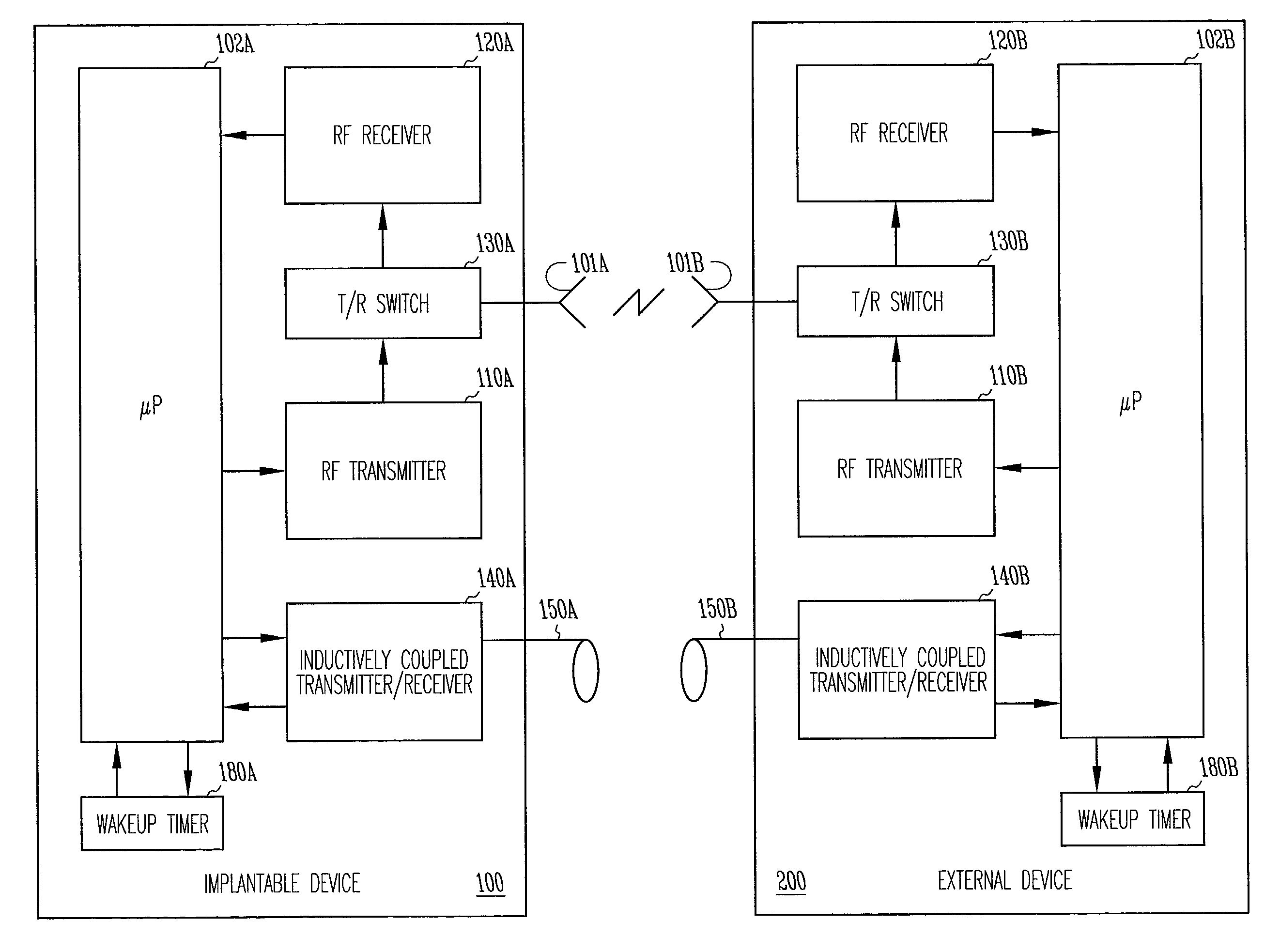

Embodiment Construction

[0025]The present invention includes a system and method for providing far-field RF telemetry between an implantable medical device and an external device in which power consumption is lessened by managing the duty cycles of the RF transmitting and receiving components. As used herein, the term data includes digital data and analog signals.

[0026]FIG. 1 shows selected telemetry components of external device 200 and implantable medical device 100. In this functional block diagram, the components are shown as being substantially identical in each device, however, in one embodiment, the components differ. In this exemplary embodiment, implantable medical device 100 and external device 200 are microprocessor-based devices with implantable medical device 100 having controller 102A and external device 200 having controller 102B. Controllers 102A and 102B each include a microprocessor and memory for data and program storage that supervises overall device operation as well as telemetry. In o...


PUM


Abstract

A telemetry system enabling radio frequency (RF) communications between an implantable medical device and an external device, or programmer, in which the RF circuitry is normally maintained in a powered down state in order to conserve power. At synchronized wakeup intervals, one of the devices designated as a master device powers up its RF transmitter to request a communications session, and the other device designated as a slave device powers up its RF transmitter to listen for the request. Telemetry is conducted using a far field or near field communication link.

Description

TECHNICAL FIELD[0001]In general, the present subject matter relates to implantable medical devices, such as cardiac pacemakers and cardioverter / defibrillators, and in particular, the present subject matter relates to wireless telemetry with implantable medical devices.BACKGROUND[0002]Implantable medical devices, including cardiac rhythm management devices such as pacemakers and implantable cardioverter / defibrillators, typically have the capability to communicate data with a device called an external programmer, or programmer, via a radio frequency telemetry link. A clinician may use such a programmer to program the operating parameters of an implanted medical device. For example, the pacing mode and other operating characteristics of a pacemaker may be modified after implantation in this manner. Modern implantable medical devices also include the capability for bidirectional communication so that information can be transmitted to the programmer from the implanted device. Among the d...

Claims


Application Information

Patent Timeline
IPC IPC(8): A61N1/10A61N1/08A61N1/372A61N1/39
CPCA61N1/08A61N1/37276A61N1/37223A61N1/3956
Inventor VON ARX, JEFFREY A.BALCZEWSKI, RONMAZAR, SCOTT T.LINDER, WILLIAM J.MASS, WILLIAM R.
Owner CARDIAC PACEMAKERS INC
Learn More