Vibrating type compressor

a compressor and vibration type technology, applied in the direction of dynamo-electric machines, piston pumps, magnetic circuit shapes/forms/construction, etc., can solve the problems of reducing affecting the efficiency of vibration type compressors, and unable to ensure the orientation of grains. the effect of permanent magnetic flux, effective use and improved efficiency

Inactive Publication Date: 2006-02-07
SAWAFUJI ELECTRIC COMPANY
View PDF13 Cites 10 Cited by
  • Summary
  • Abstract
  • Description
  • Claims
  • Application Information

AI Technical Summary

Benefits of technology

[0037]Because the permanent magnet is firmly fixed to the core pole side and because from the relation between cost and magnetic properties of the permanent magnet, the permanent magnet is divided by an optimum number of division, a neodymium magnet or rare-earth magnet having a high permanent magnetic flux density Br can be effectively used and the efficiency of the vibration type compressor can be improved.

Problems solved by technology

However, because the neodymium magnet or rare-earth magnet used here has high performance and a high permanent magnetic flux density Br, the manufacturing of a magnet poses drawbacks as described below:
(1) During the forming performed by applying a magnetic field to make the orientation of the whole of the grains a radial direction, the orientation of the grains cannot be sufficiently ensured because of a small sectional area of the inside diameter of the magnet and obtained properties are inferior to the original characteristics of the material for the magnet.
In this shape, i.e., the cylindrical shape, it is difficult to obtain a size by polishing the inside diameter and hence the cost becomes high.
On the other hand, a conventional method of fixing by use of a screw cramp between the outer core 73 and the cylinder block 83 which is used in a conventional vibration type compressor offers drawbacks as described below:
(4) When the diameter is increased as described in and above, the outer core 73 becomes thicker than necessary although the original function of the outer core is to allow a magnetic flux to pass, with the result that the weight and direct material cost increase.
(5) The working cost increases by making a hole and a screw hole in the outer core 73 and the cylinder block 83.
(6) Even when the diameter of the outer core 73 is optimized as in , because of the use of another piece the working cost and direct material cost increase by this amount.
(7) In the case of screw cramping of the cylinder block 83 to the outer core 73, it is necessary to perform uniform tightening by use of three or four screws. If this is impossible, the cylinder block 83 and the resonance springs 76, 77 come into non-uniform contact and this may cause poor performance. Therefore, due care should be used in assembling.
In short, the direct material cost and working cost increase, increases in weight and assembling becomes difficult.

Method used


Image

  • Vibrating type compressor
  • Vibrating type compressor
  • Vibrating type compressor

Examples


Embodiment Construction

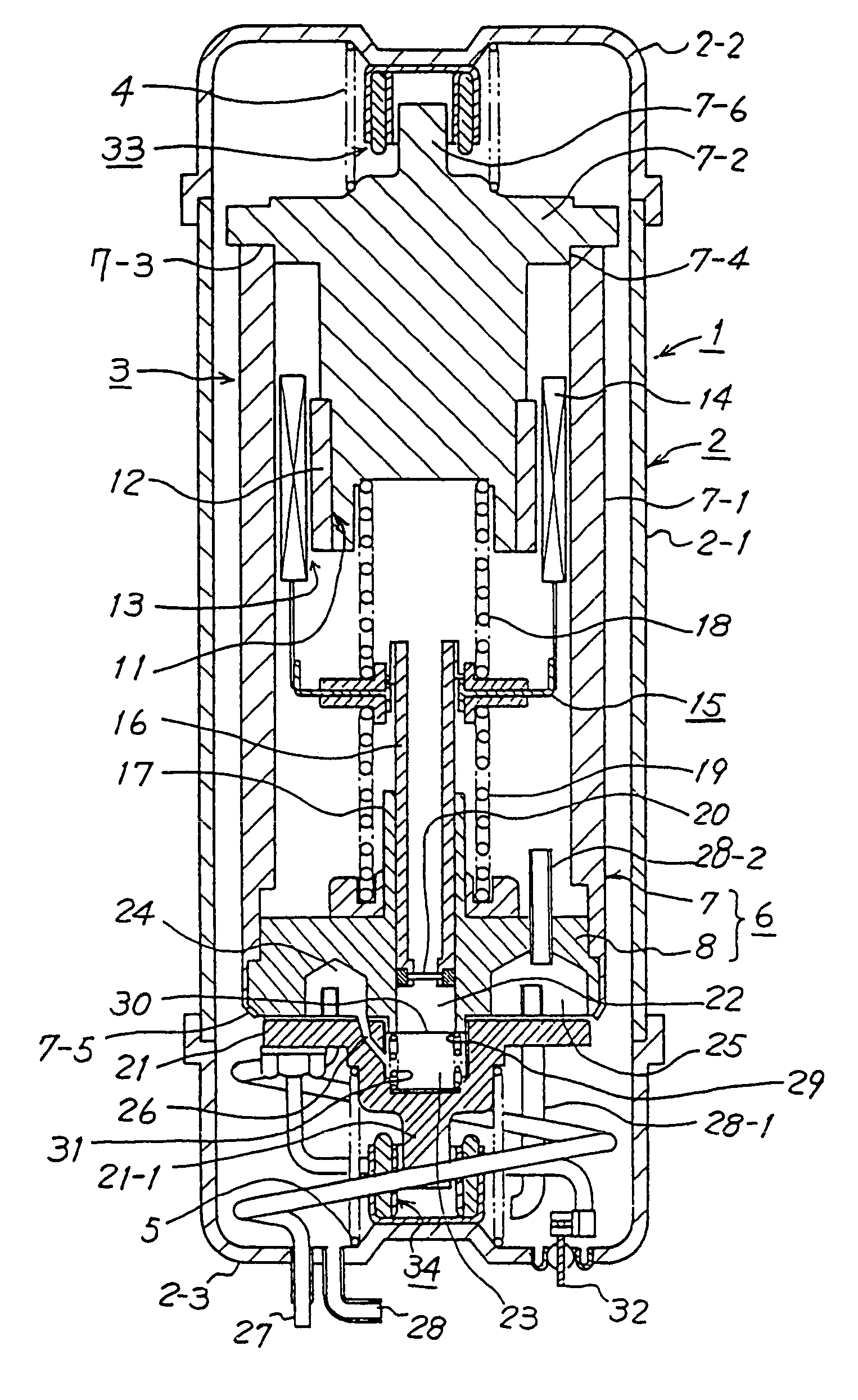
[0067]FIG. 1 shows a sectional view of an embodiment of a vibration type compressor related to the present invention.

[0068]In this figure, a vibration type compressor 1 is configured in such a manner that within a cylindrical gastight vessel 2 constituted by a cylinder 2-1 and covers 2-2, 2-3 which close both opening ends of the cylinder 2-1, a compressor main body 3 is elastically supported by use of springs 4, 5 etc.

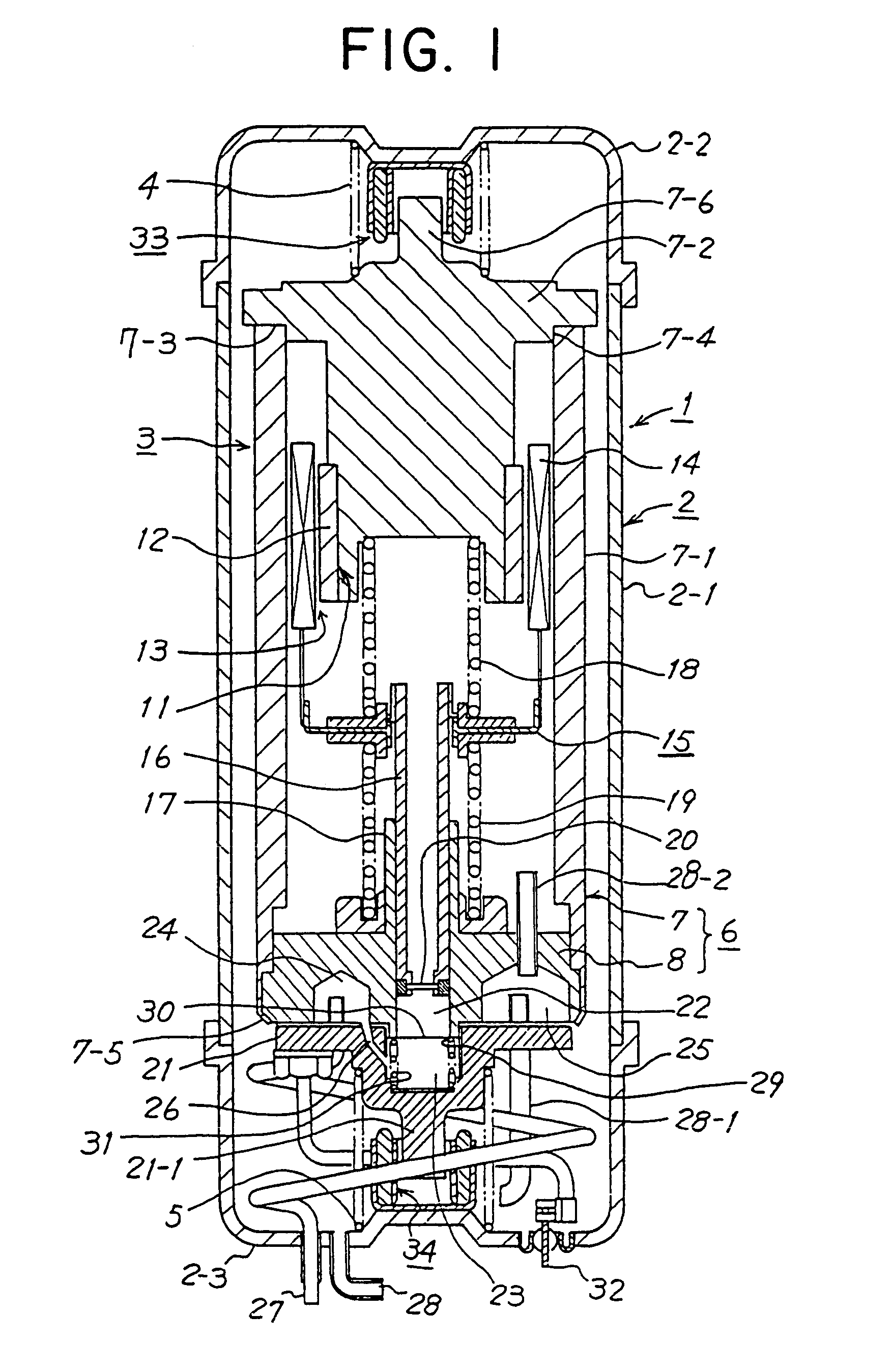
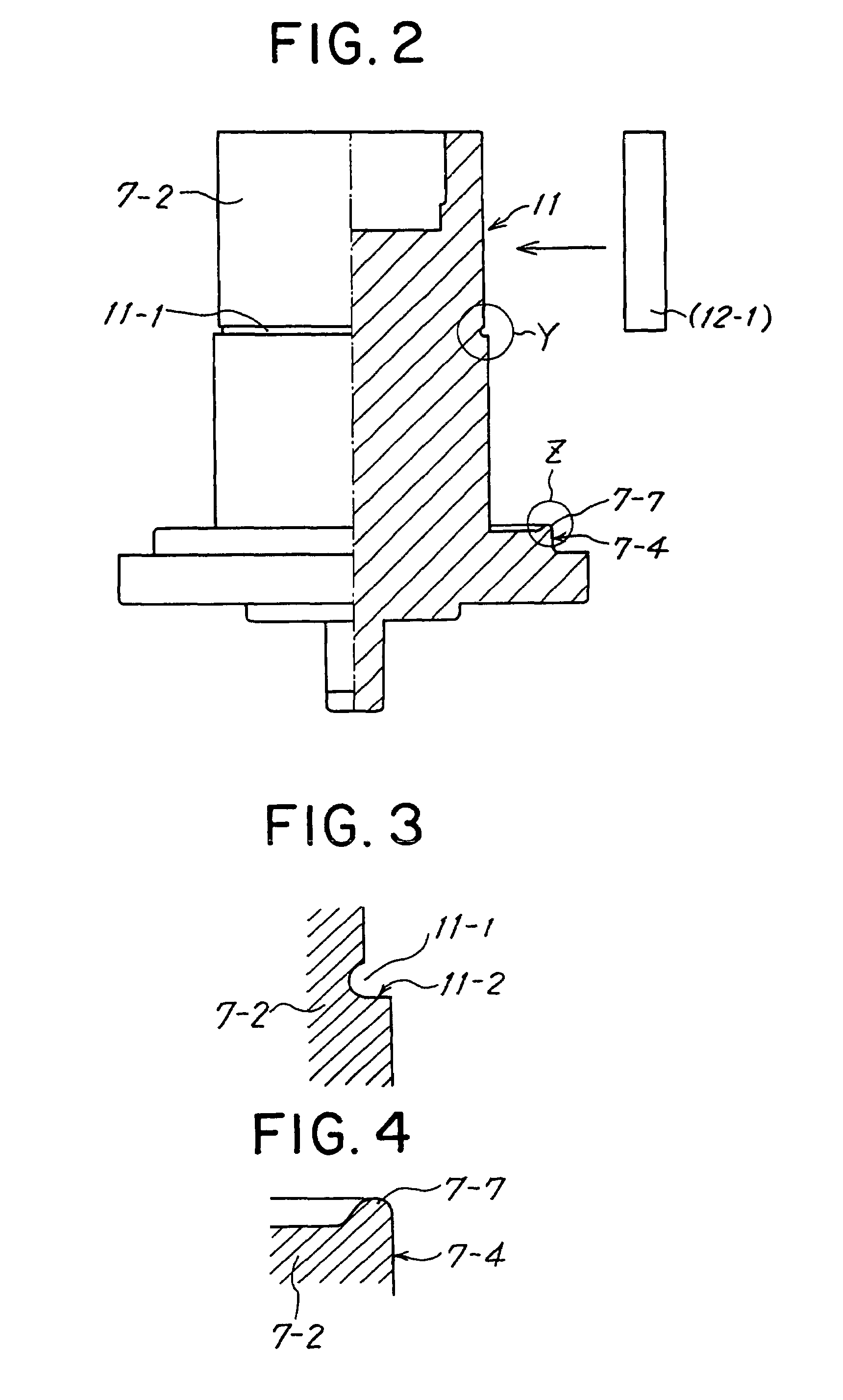
[0069]A casing 6 of the compressor main body 3 is configured in such a manner that there are fixed a magnetic path member 7, i.e., an assembly of a cylindrical yoke 7-1 which is an outer core and of a core pole 7-2 which is a flanged inner core closing an end, i.e., the top end of the yoke 7-1 provided with a coaxial cylindrical body protruding to inside, and a cylinder block 8 at the other end, i.e., the bottom end of the magnetic path member 7.

[0070]In an upper portion of the core pole 7-2 are formed a stepped portion 7-3 which perpendicularly intersects the inner ci...


PUM


Abstract

A vibration type compressor related to the present invention, in which a compressor main body 3 is built into a gastight vessel 2 including a yoke 7-1, a magnetic path member 7 formed from a column-shaped core pole 7-2, a permanent magnet 12 arranged in the magnetic path, an electromagnetic coil 14 which is arranged within an annular magnetic gap 13 between the magnetic path members 7 by being supported by a mechanical vibration system to as to be able to vibrate and is wound around a lead plate to perform the connection treatment of a terminal thereof, a piston 16 connected to the electromagnetic coil 14, and a cylinder block 8 which closes the yoke 7-1 and in the interior of which is formed the cylinder portion 17 housing the piston 16, characterized in that the permanent magnet 12 is formed from a neodymium magnet or a rare-earth magnet and in that the cylindrical permanent magnet 12 is divided into four parts in the axial direction thereof, the four-part divided magnet being bonded and fixed to the side of the core pole 7-2, whereby the vibration type compressor is miniaturized and its efficiency is increased.

Description

FIELD OF THE INVENTION[0001]The present invention relates to a vibration type compressor and, more particularly, to a vibration type compressor built into a gastight vessel, in particular, for use in a refrigerator etc., which vibration type compressor comprises a bottomed, cylindrical outer core, an inner core which, along with the outer core, constitutes a magnetic path (a core pole), a permanent magnet disposed in the inner core of the magnetic path in a form divided into a plurality of parts, an electromagnetic coil which is disposed in an annular gap formed by the permanent magnet and the outer core and is supported by a mechanical vibration system so as to be able to vibrate, a piston connected to the electromagnetic coil, and a cylinder block housing the piston, and which vibration type compressor compresses a low-pressure refrigerant flowing into the gastight vessel and delivers a high-pressure refrigerant by supplying an alternating current to the electromagnetic coil, ther...

Claims


Application Information

Patent Timeline
Patent Type & Authority Patents(United States)
IPC IPC(8): F04B35/04H02K33/18
CPCF04B35/045H02K33/18H02K1/34
Inventor FUJISAWA, YOSHIAKIHASEGAWA, TAKEHIRO
Owner SAWAFUJI ELECTRIC COMPANY
Why Eureka
Try Eureka