Liquid fuel reservoir for fuel cells

Inactive Publication Date: 2006-02-07
FOAMEX INNOVATIONS OPERATING +1
View PDF87 Cites 53 Cited by
  • Summary
  • Abstract
  • Description
  • Claims
  • Application Information

AI Technical Summary

Benefits of technology

[0024]The wicking material can be permanently or reversibly compressed to from the wicking structure. An example of a permanently compressed wicking material is a felted wicking material. An example of a reversibly compressed wicking structure is a wicking structure formed by compressing a wicking material while the wicking material is being put into the cavity of a container, so that structures such as the walls of the container help keep the wicking material in a compressed state while the wicking material is inside the container.
[0025]In a particularly preferred embodiment, the wicking structure is made with a foam with a capillarity gradient, such that the flow of the liquid fuel is directed from one region of the structure to another region of the structure as a result of the differential in capillarity between the two regions. One method for producing a foam with a cap

Problems solved by technology

Cross-over results in a short circuit in the cell since the electrons resulting from the oxidation reaction do not follow the current path between the electrodes.
The problem is particularly ac

Method used


Image

  • Liquid fuel reservoir for fuel cells
  • Liquid fuel reservoir for fuel cells
  • Liquid fuel reservoir for fuel cells

Examples


Embodiment Construction

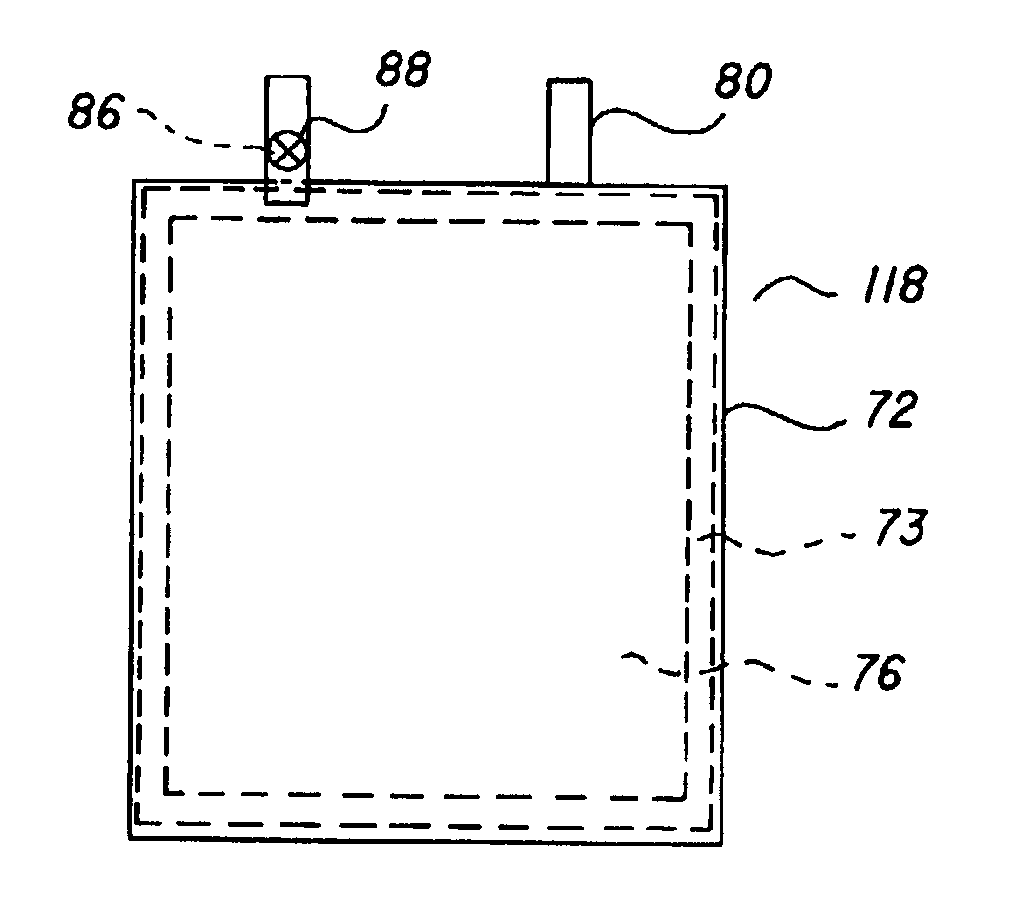
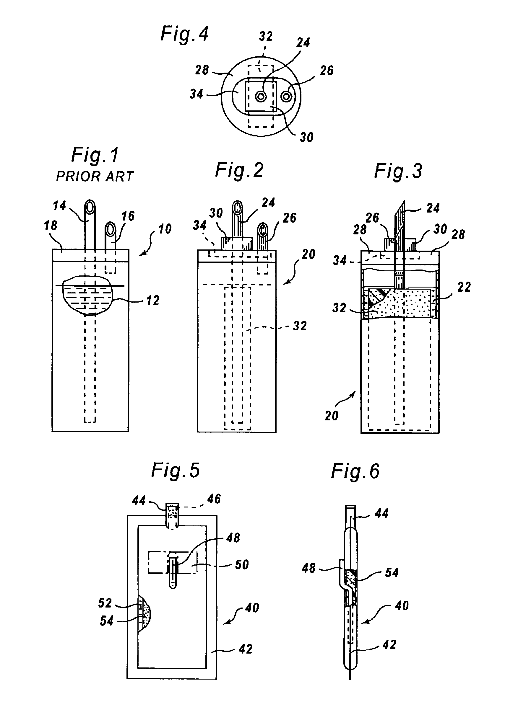
[0061]Referring first to FIGS. 2 to 4, a cartridge container 20 defines a cavity holding a liquid fuel mixture 22. An outlet tube 24 extends into the container 20 through a cover 28 and the outlet tube 24 communicates between the cavity of the container 20 and outside of the container. An air inlet tube 26 also extends into the container 20 through cover 28. The air inlet tube 26 may include a one way valve (not shown) so as to prevent liquid from flowing from the container 20.

[0062]A wicking structure 32 is provided within the cavity of the container 20. The wicking structure 32 surrounds the open end of the outlet tube 24 within the cavity of the container 20. Liquid fuel wicks into the wicking structure 32.

[0063]In the embodiment shown in FIGS. 2 to 4, the wicking structure is a felted polyurethane foam shaped as a rectangular cube or box. For example, the structure is approximately 10 mm (width)×5 mm (thickness)×90 (height) mm, with the 90 mm height as the longest dimension of t...


PUM


Abstract

The present invention concerns a fuel reservoir for a liquid fuel cell particularly useful for portable electronic devices in which the fuel reservoir can deliver the liquid fuel regardless of the orientation. The fuel reservoir comprises (a) a container defining a cavity for holding the liquid fuel; (b) a wicking structure positioned within the cavity and into which at least a portion of the liquid fuel wicks and from which said liquid fuel subsequently may be discharged or delivered, such as by pumping or wicking. The wicking structure is formed from a wicking material with a free rise wick height greater than at least one half of the longest dimension of the wicking structure. Among materials with such wicking capability are foams, matted, bundled or woven fibers and nonwoven fibers. The container may have a generally flat and thin profile, formed as a pouch or envelope with substantially planar top and bottom faces of flexible film material, such that the container holding the wicking structure and filled with the liquid fuel can be bent or shaped.

Description

[0001]This application claims the benefit of U.S. Provisional Patent Application No. 60 / 509,035, entitled “Liquid Fuel Delivery System for Fuel Cells”, filed on Jun. 28, 2001 by the instant inventors, the disclosure of which is incorporated by reference.[0002]This invention relates to liquid fuel cells in which the liquid fuel is indirectly or preferably directly oxidized at the anode. In particular, it relates to the reservoir for holding and metering or delivering the liquid fuel to the anode of a liquid fuel cell. This invention also relates to liquid fuel feed systems for micro fuel cell reformers.BACKGROUND OF THE INVENTION[0003]Electrochemical fuel cells convert reactants, namely fuel and oxidants, to generate electric power and reaction products. Electrochemical fuel cells generally employ an electrolyte disposed between two electrodes (an anode and a cathode). An electrocatalyst is needed to induce the desired electrochemical reactions at the electrodes. Liquid feed solid po...

Claims


Application Information

Patent Timeline
IPC IPC(8): H01M2/00H01M8/02H01M8/04H01M8/10
CPCH01M8/04208H01M8/04216H01M8/1011F17C2270/0763Y02E60/523H01M2008/1095H01M2250/30Y02B90/18H01M8/1013Y02B90/10Y02E60/50
Inventor KINKELAAR, MARK R.THOMPSON, ANDREW
Owner FOAMEX INNOVATIONS OPERATING
Why Eureka
Try Eureka