Light-emitting unit and method for producing same as well as lead frame used for producing light-emitting unit
Inactive Publication Date: 2006-02-07
HITACHI CABLE +1
View PDF4 Cites 320 Cited by
Summary
Abstract
Description
Claims
Application Information
AI Technical Summary
This helps you quickly interpret patents by identifying the three key elements:
Problems solved by technology
Method used
Benefits of technology
[0060]According to such arrangement as described above of the invention, light-emitting efficiency in the
Problems solved by technology
As a result, a height T from a mount surface becomes high in the case when the light-emitting unit is mounted on a mount board, so that it is difficult to downsize an electronic device in which the above-described light-emitting unit has been used.
However, a through hole mount type light-emitting unit as shown in FIGS. 1(a) and 1(b) in the above-described prior art has involved such a problem that it is difficult to downsize the unit, so that it is also difficult to downsize an electronic device wherein the above-described light-emitting unit has been used.
In this connection, however, there may occur such a problem as mentioned below, because a coefficient of thermal conductivity in an insulating substrate 1201 is low.
When the light-emitting diode 1 retains heat and it becomes high-temperature, there arises such a problem that electrical characteristics of the light-emitting diode 1 change, so that light-emitting efficiency decreases.
Moreover, since a reflection member 11 prepared in a separate process from that of preparing the wiring board 12 has been bonded, there has been such a problem that manufacturing processes and the number of parts to be used increase, so that its manufactures' costs increase also.
Furthermore, it is difficult to make an insulating subst
Method used
Image
Click on the blue label to locate the original text in one second.
Reading with bidirectional positioning of images and text.
Examples
Example
EXAMPLE 1
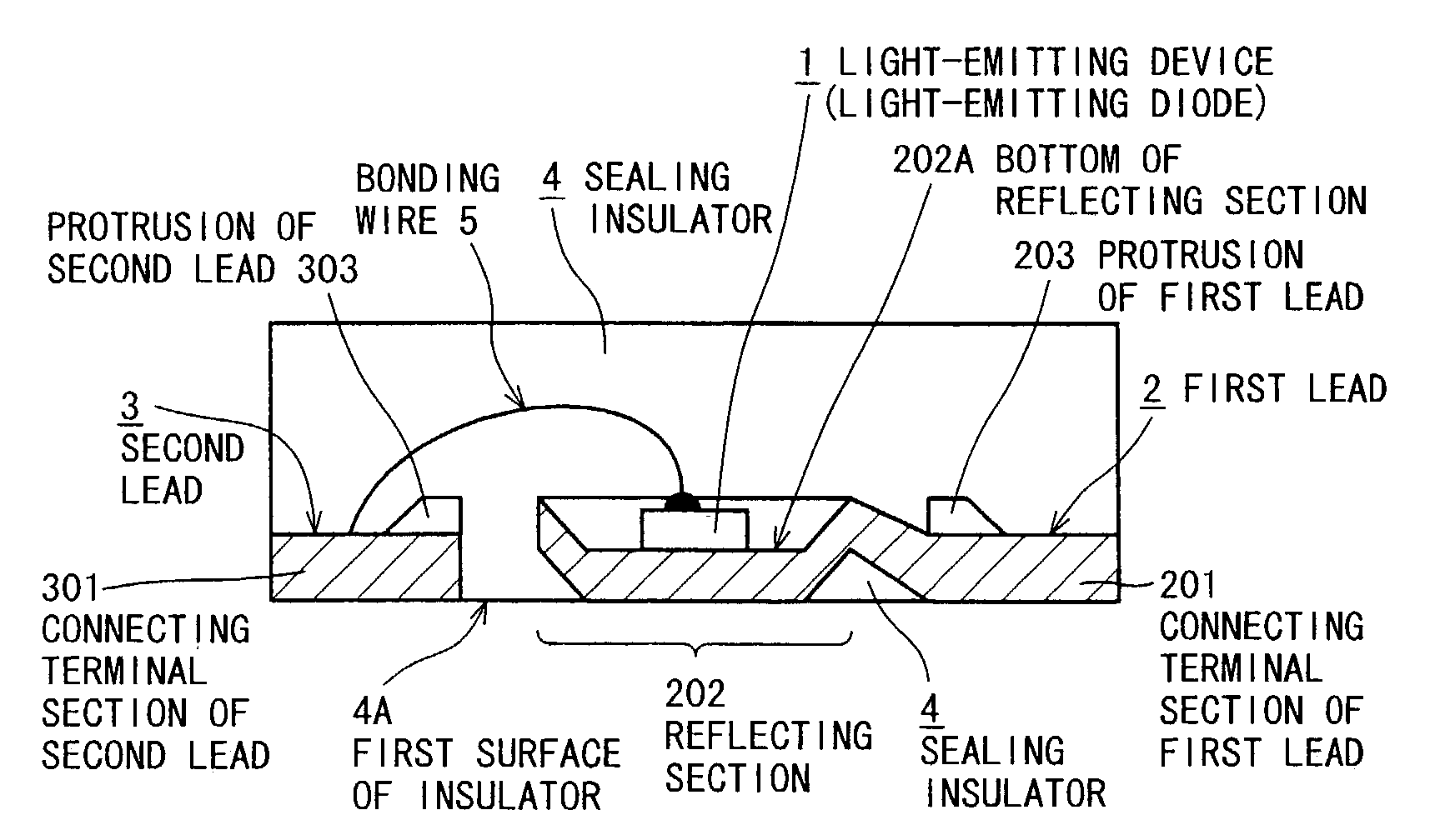
[0088]Both of FIGS. 3(a) and 3(b) as well as FIGS. 4(a) and 4(b) are schematic views each showing an outlined constitution of a light-emitting unit according to example 1 of the present invention wherein FIG. 3(a) is a plan view showing the whole light-emitting unit, FIG. 3(b) is a sectional view taken along the line A–A′ of FIG. 3(a), FIG. 4(a) is an enlarged sectional view showing a first lead of FIG. 3(b), and FIG. 4(b) is a sectional view taken along the line B–B′ of FIG. 3(a).
[0089]In FIGS. 3(a) and 3(b), reference numeral 1 designates a light-emitting device, 2 a first lead, 201 a connecting terminal section for the first lead, 202 a reflecting section, 202A the bottom of the reflecting section, 202B a side of the reflecting section (reflective surface), 203 protrusions of the first lead, 3 a second lead, 301 a connecting terminal section for the second lead, 303 protrusions of the second lead, 4 an insulator, 4A a first surface of the insulator, 5 a bonding wire, and...
Example
EXAMPLE 2
[0137]FIGS. 15(a) and 15(b) are schematic views each showing an outlined constitution of a light-emitting unit according to example 2 of the present invention wherein FIG. 15(a) is a plan view showing the whole light-emitting unit, and FIG. 15(b) is a sectional view taken along the line L–L′ of FIG. 15(a).
[0138]In FIGS. 15(a) and 15(b), reference numeral 1 designates a light-emitting device, 2 a first lead, 201 a connecting terminal section of the first lead, 202 a reflecting section, 202A the bottom of the reflecting section, 202B a side of the reflecting section (reflective surface), 203 a protrusion of the first lead, 204 a folded portion of the first lead, 3 a second lead, 301 a connecting terminal section of the second lead, 303 a protrusion of the second lead, 304 a folded portion of the second lead, 4 an insulator, 4A a first surface of the insulator, 4B a second surface of the insulator, 4C a third surface of the insulator, and 5 a bonding wire, respectively.
[0139]T...
PUM
Abstract
A surface mount type light-emitting unit composed of a light-emitting device, a first lead connected electrically with a first electrode of the light-emitting device, a second lead connected electrically with a second electrode of the light-emitting device, and a clear insulator for sealing the light-emitting device, a connecting section of the first electrode of the light-emitting device and the first lead, and a connecting section of the second electrode of the light-emitting device and the second lead wherein connecting terminal sections of the first and second leads for connecting them with external devices, respectively, are placed on a surface of the insulator, comprises an end of the first lead being molded into a cup-shaped portion having a flat bottom; the light-emitting device being bonded to the bottom inside a reflecting section corresponding to the molded cup-shaped portion of the first lead; and a surface opposed to that of the reflecting section on which the light-emitting device has been bonded being exposed to the surface of the insulator.
Description
BACKGROUND OF THE INVENTION[0001]1. Field of the Invention[0002]The present invention relates to a light-emitting unit, and a method for producing the same as well as a lead frame used for the light-emitting unit, and more particularly to an effective technology applied to a surface mount type light-emitting unit wherein a light-emitting device such as light-emitting diode (LED) has been used.[0003]2. Prior Art[0004]Heretofore, a light-emitting unit wherein a light-emitting device such as light-emitting diode is used has been utilized for a variety of pilot lamps, a backlight for display devices and liquid crystal display, an exposure light source for printer head, optical communications and the like extending over a wide range. There are two types of the above-described light-emitting unit, one of which is a through hole mount type unit wherein a first lead (cathode) and a second lead (anode) are inserted into through holes in a mount board, and they are soldered, respectively; and...
Claims
Application Information
Patent Timeline
Application Date:The date an application was filed.
Publication Date:The date a patent or application was officially published.
First Publication Date:The earliest publication date of a patent with the same application number.
Issue Date:Publication date of the patent grant document.
PCT Entry Date:The Entry date of PCT National Phase.
Estimated Expiry Date:The statutory expiry date of a patent right according to the Patent Law, and it is the longest term of protection that the patent right can achieve without the termination of the patent right due to other reasons(Term extension factor has been taken into account ).
Invalid Date:Actual expiry date is based on effective date or publication date of legal transaction data of invalid patent.