Method and apparatus for determining properties of an electrophoretic display

a technology of electrophoretic display and method, applied in the field of electrophoretic display, can solve the problems of increasing display cost, complicating manufacturing process, and external sensors not accurately measuring the parameters inside the display

Inactive Publication Date: 2006-02-07
E INK CORPORATION
View PDF32 Cites 592 Cited by
  • Summary
  • Abstract
  • Description
  • Claims
  • Application Information

AI Technical Summary

Benefits of technology

[0011]The primary optical effect in a microencapsulated electrophoretic display device is the controlled positioning of one or more types of colloidal particles within a microcapsule. In one embodiment, colloidal particles are suspended in a colored fluid within the microcapsule. Application of an electrical signal will drive the particles to one side of the microcapsule or the other. If the colloidal particles are near the side of the microcapsule nearer the viewer, the viewer will see the color of the colloid. If the colloidal particles are nearer the opposite side of the microcapsule from the viewer, the viewer will see the colored fluid. The contrast between the colors of the fluid and the colloid, based on the colloid position, provides the means for a display device.

Problems solved by technology

Use of external display sensors, however, may increase cost of the display and complicate the manufacturing process.
In addition, external sensors may not accurately measure the parameters inside the display.

Method used


Image

  • Method and apparatus for determining properties of an electrophoretic display
  • Method and apparatus for determining properties of an electrophoretic display
  • Method and apparatus for determining properties of an electrophoretic display

Examples


example 1

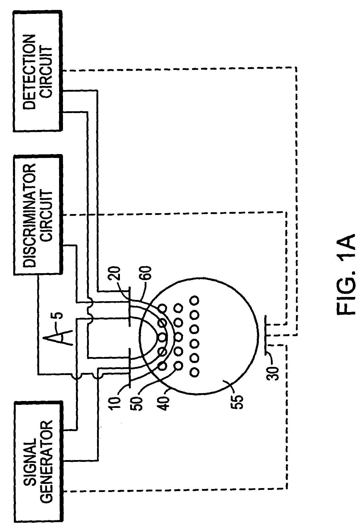
[0045]A microencapsulated electrophoretic display comprising rutile titania dispersed in a low dielectric constant hydrocarbon fluid was provided. Two electrodes were positioned adjacent each other on the same substrate, adjacent also to a microcapsule, and on the back side of the display from the viewer. An AC electrical signal was placed across the electrodes, and the current passed between the electrodes measured. The frequency of the AC signal was set so that the capacitive characteristics of the microcapsules were measured. Typically, electrical frequencies in the range of 10 Hz to 10 KHz are useful in this regard. The dielectric constant near the electrodes depended on whether the colloid was on the same side of the microcapsule as the electrodes, or on the opposite sides. It is advantageous to have the spacing of the electrodes small compared to the microcapsule diameter. A high dielectric constant indicated that the colloidal particles were near the electrodes, and the displ...

example 2

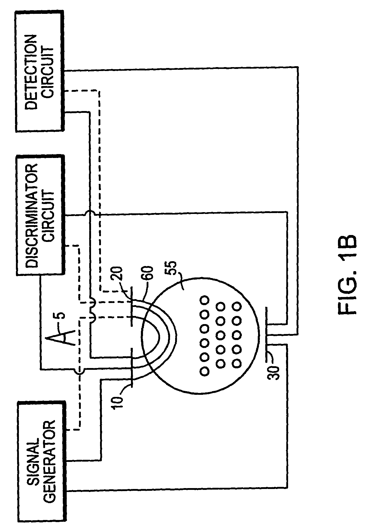
[0046]A microencapsulated electrophoretic display was constructed with sensing electrodes on opposing sides of the display. These electrodes could be separate structures, or could be the same electrodes used to address the display. The colloidal dispersion was constructed so that the colloid contains a net negative charge. A negative charge is placed on the front electrode, sufficient to address some or all of the pixel. If the colloid is near the front of the microcapsule, the colloid will be repelled from the front surface and attracted to the back. The movement of the colloid gives a characteristic current signal, which rises, peaks, and then diminishes as the colloid transits the cell. This peak has a characteristic time constant and amplitude, depending on the display characteristics. For example, in a display which requires 90 V to address and a cell gap of 100 microns, the colloid transits in the range of 100 ms to 2 seconds, depending on the formulation.

[0047]Alternatively, ...

example 3

[0050]The case of example 2, except the electrodes were adjacent as single side of the display, and spaced close together relative to the microcapsule size. Application of a voltage in the range of 1 V to 100 V causes some of the colloid to move from one electrode to the other if the colloid is near the surface of microcapsule adjacent the electrodes. If the colloid is on the other side of the microcapsule, no such transit will be seen. The discriminator circuit looks for the presence or absence of a current representing the colloidal particles, and thus determine if the colloid is on the face nearer or further from the electrodes. This method has the advantage of not disturbing the relative position of the colloid in the front or back of the display.

[0051]While the examples described here are listed using encapsulated electrophoretic displays, there are other particle-based display media which should also work as well, including encapsulated suspended particles and rotating ball di...


PUM

PropertyMeasurementUnit
diametersaaaaaaaaaa
voltagesaaaaaaaaaa
voltagesaaaaaaaaaa

Abstract

A method for sensing the state of an electrophoretic display includes the steps of applying an electrical signal to a display element, measuring an electrical response for the display element, and deducing the state of the display element from the measured electrical response. Also, the parameters of the display materials are determined using the encapsulated electrophoretic display media as a sensor, either alone or in conjunction with other sensors.

Description

CROSS-REFERENCE TO RELATED APPLICATIONS[0001]This application is a continuation of U.S. application Ser. No. 10 / 277,527, filed Oct. 22, 2002, now abandoned, which is continuation of and claims priority to U.S. Ser. No. 10 / 277,527 filed Oct. 22, 2002, which is a continuation-in-part of and claims priority to U.S. Ser. No. 09 / 349,808 filed Jul. 8, 1999, now U.S. Pat. No. 6,512,354, which claims priority to U.S. Ser. No. 60 / 092,046 filed Jul. 8, 1998, the entire disclosure of each application being incorporated by reference herein.FIELD OF THE INVENTION[0002]The present invention relates to electronic displays and, in particular, to methods and apparatus for determining properties of electrophoretic displays.BACKGROUND OF THE INVENTION[0003]Electrophoretic display media, generally characterized by the movement of particles through an applied electric field, are highly reflective, can be made bistable, can be scaled to a large area, and consume very little power. Encapsulated electropho...

Claims


Application Information

Patent Timeline
Patent Type & Authority Patents(United States)
IPC IPC(8): G01N27/00G01R31/00B41J3/407G02B26/02G02F1/167G02F1/1685G09G3/34H01L27/28H01L51/00H01L51/05H01L51/30
CPCB41J3/4076G02B26/026G02F1/167H01L27/28G09G3/344H01L51/0512H01L51/005H01L51/0077G09G2320/029G02F1/1685H10K19/00H10K85/60H10K85/30H10K10/462
Inventor JACOBSON, JOSEPH M.DRZAIC, PAULO'NEIL, STEVEN J.GATES, HOLLY G.ABRAMSON, JUSTIN
Owner E INK CORPORATION
Why Eureka
Try Eureka