
Measurement of a coating on a composite using capacitance

a composite material and capacitance technology, applied in the direction of capacitance measurement, resistance/reactance/impedence, instruments, etc., can solve the weight limit of components on a mobile platform, the thickness of non-metallic coatings on these materials is difficult to measure, and the coating may need to be removed and recoated

Inactive Publication Date: 2006-02-07
THE BOEING CO
View PDF15 Cites 6 Cited by
  • Summary
  • Abstract
  • Description
  • Claims
  • Application Information

AI Technical Summary

Benefits of technology

This method accurately measures the thickness of non-conductive coatings on semi-conductive substrates with reduced labor costs and risk of damage, providing precise and uniform measurements without disassembly, enhancing the efficiency and reliability of coating thickness control.

Problems solved by technology

For example, there may be a weight limit for components on a mobile platform, such as an aircraft, train, bus or ship that are required to be coated with a primer.
Often such components arrive from suppliers uncoated and near maximum weight.
The thickness of non-metallic coatings on these materials is difficult to measure since the substrate, i.e. the uncoated object or component, is only semi-conductive at best.
If the coating is suspected of being too thick or uneven, the coating may need to be removed and recoated.
This can cause significant increase in the labor costs of measuring the thickness of the coating and significant increase in the risk of damage to the substrate / component.
However, typically ultrasonic measurement systems are not sufficiently reliable to accurately measure the thickness of thin film coatings such as paint.
In addition, the nature of ultrasonic measurement requires the technician to interpret complex waveforms that require extensive training and certification.

Method used


Image

  • Measurement of a coating on a composite using capacitance
  • Measurement of a coating on a composite using capacitance
  • Measurement of a coating on a composite using capacitance

Examples


Embodiment Construction

[0014]The following description of the preferred embodiments is merely exemplary in nature and is in no way intended to limit the invention, its application or uses. Additionally, the advantages provided by the preferred embodiments, as described below, are exemplary in nature and not all preferred embodiments provide the same advantages or the same degree of advantages.

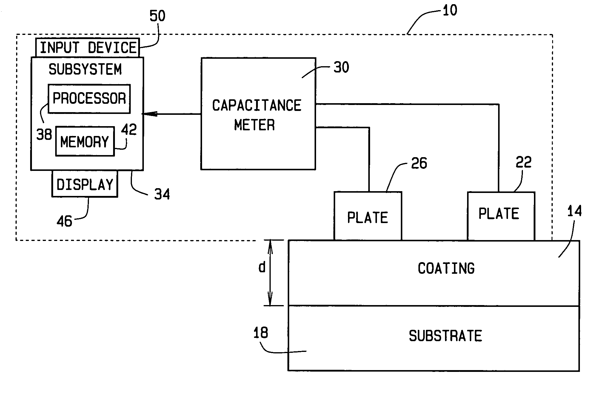
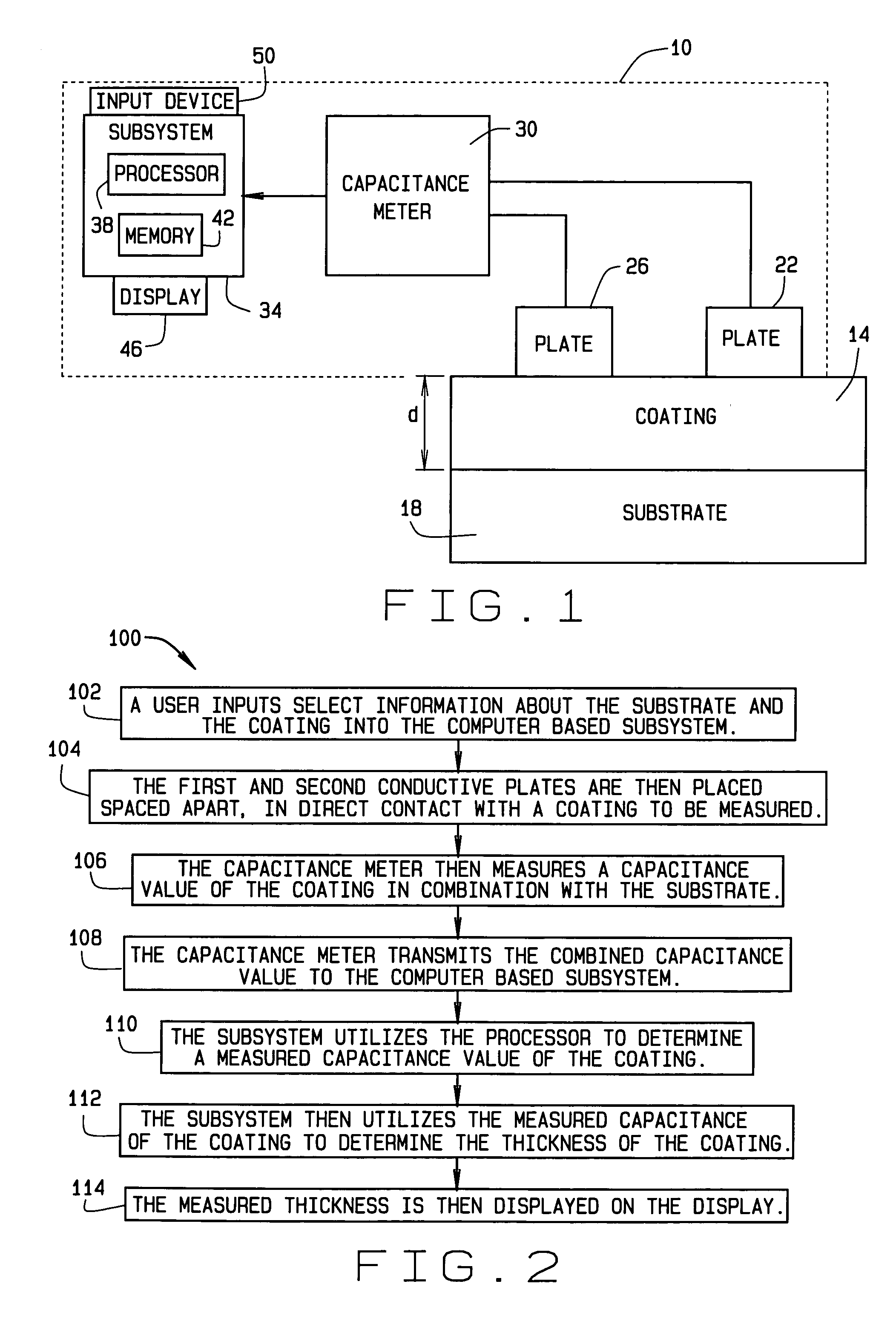
[0015]FIG. 1 is a block diagram of a system 10 for measuring a thickness d of a coating 14 on a substrate 18, in accordance with a preferred embodiment of the present invention. In a preferred embodiment the coating 14 is comprised of a non-conductive material and the substrate 18 is constructed of a semi-conductive material or compound. Additionally, in a preferred embodiment, the coating 14 is a non-conductive coating, such as paint, and the substrate 18 is a component of a mobile platform constructed of a semi-conductive composite. For example, the semi-conductive composite substrate 18 can be a control surface co...


PUM


Abstract

A method for measuring a thickness of a non-conductive coating on a semi-conductive substrate includes placing a pair of conducting plates in contact with the non-conductive coating. A capacitance value of the non-conductive coating in combination with the semi-conductive component is measured using a capacitance meter. The measured capacitance value of the non-conductive coating in combination with the semi-conductive component is then used to determine an independent capacitance value of the non-conductive coating. The thickness of the non-conductive coating is directly related to the independent capacitance value of the non-conductive coating.

Description

FIELD OF INVENTION[0001]The invention relates generally to measuring the thickness of a film coating on a substrate. More specifically, the invention relates to measuring the thickness of a non-metallic film coating on a semi-conductive substrate.BACKGROUND OF THE INVENTION[0002]Coated surfaces are ubiquitous in today's society. Objects from integrated circuit boards, to optical lenses, to counter tops, to aircraft have coated surfaces. The surfaces may be coated with a protectant, such as an epoxy primer or a chemical barrier, or may be coated with an aesthetic layer such as paint or a decorative polymer. Often times the thickness of such coatings must be held to very strict specifications. For example, there may be a weight limit for components on a mobile platform, such as an aircraft, train, bus or ship that are required to be coated with a primer. Often such components arrive from suppliers uncoated and near maximum weight. Therefore, care must be taken to make sure that an ade...

Claims


Application Information

Patent Timeline
Patent Type & Authority Patents(United States)
IPC IPC(8): G01R27/26
CPCG01R27/2605G01B7/085
Inventor SERGOYAN, EDWARD G.JACKSON, KIRKOLSEN, ROBERT G.
Owner THE BOEING CO
Learn More