High efficiency charge pump with prevention from reverse current

a charge pump and reverse current technology, applied in the field of charge pumps, can solve the problems of inevitably produced clock signals clksub>1 /sub> and clksub>2 /sub>, and achieve the effect of enhancing the efficiency of pumping voltag

Inactive Publication Date: 2006-02-07
GLOBAL MIXED MODE TECH
View PDF16 Cites 64 Cited by
  • Summary
  • Abstract
  • Description
  • Claims
  • Application Information

AI Technical Summary

Benefits of technology

[0017]In view of the above-mentioned problems, an object of the present invention is to provide a charge pump capable of preventing from the reverse current when the clock signals are at steady states, thereby enhancing the efficiency of generating the pumping voltage.
[0018]Another object of the present invention is to provide a charge pump capable of preventing from the reverse current when the clock signals make transitions, thereby enhancing the efficiency of generating the pumping voltage.
[0022]When the first clock signal is at the first clock high level and the second former-stage clock signal is at the second former-stage clock low level, a first reverse current preventing circuit turns off the first switching circuit, thereby preventing a first steady-state reverse current from flowing through the first switching circuit out of the first capacitor.
[0024]When the second clock signal is at the second clock high level and the first former-stage clock signal is at the first former-stage clock low level, a second reverse current preventing circuit turns off the second switching circuit, thereby preventing a second steady-state reverse current from flowing through the second switching circuit out of the second capacitor.

Problems solved by technology

Under adverse effects of reverse current (or reverse charge transfer), the conventional charge pump 10 fails to achieve an efficient voltage-converting characteristic.
Although the capacitors C1 and C3 are wired to receive the same clock signal CLK1 and the capacitors C2 and C4 are wired to receive the same clock signal CLK2 in the description set forth, an amount of time delay is inevitably produced in the clock signals CLK1 and CLK2 due to signal distribution along the clock lines in practical circuit applications.

Method used


Image

  • High efficiency charge pump with prevention from reverse current
  • High efficiency charge pump with prevention from reverse current
  • High efficiency charge pump with prevention from reverse current

Examples


first embodiment

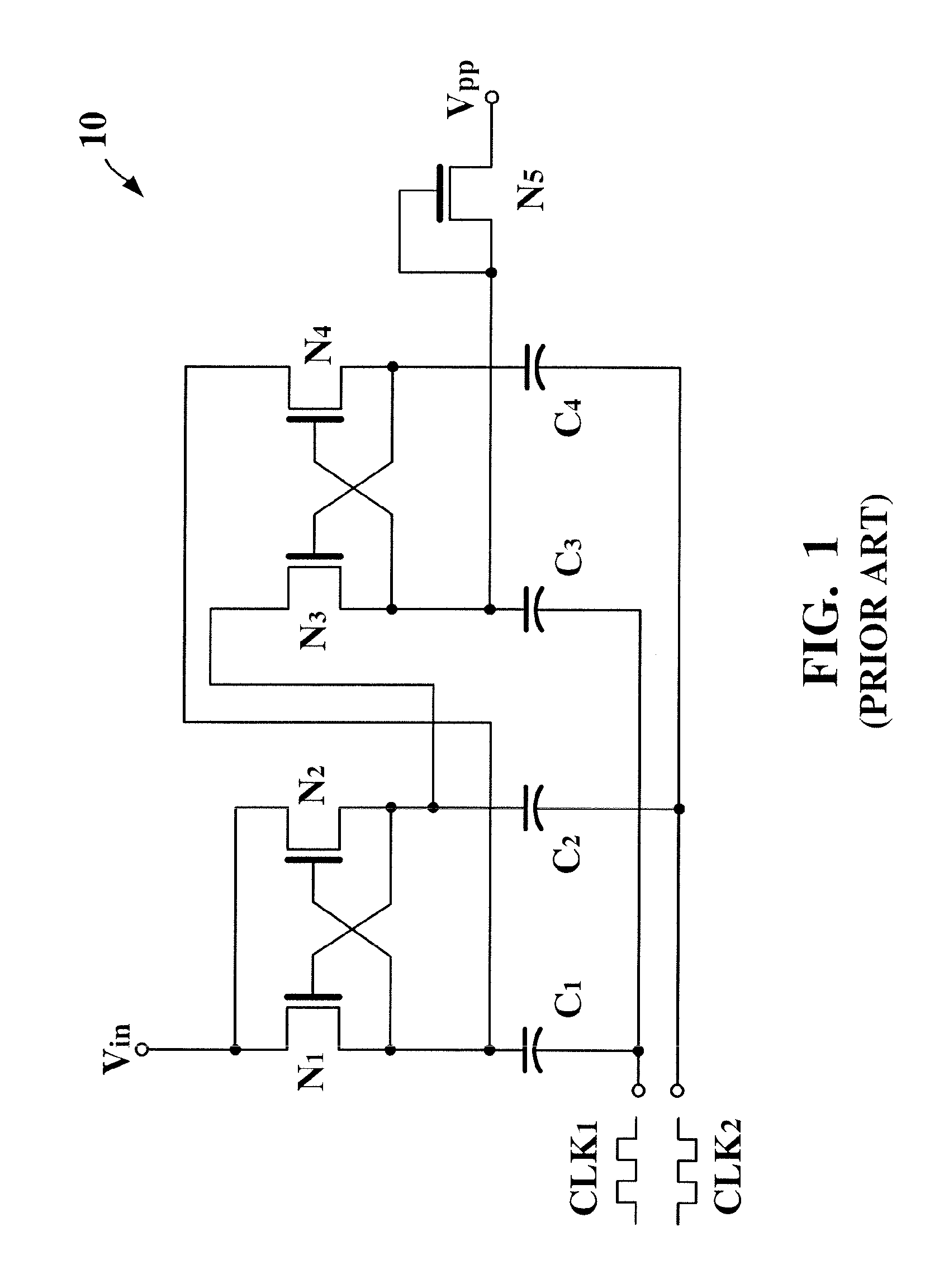
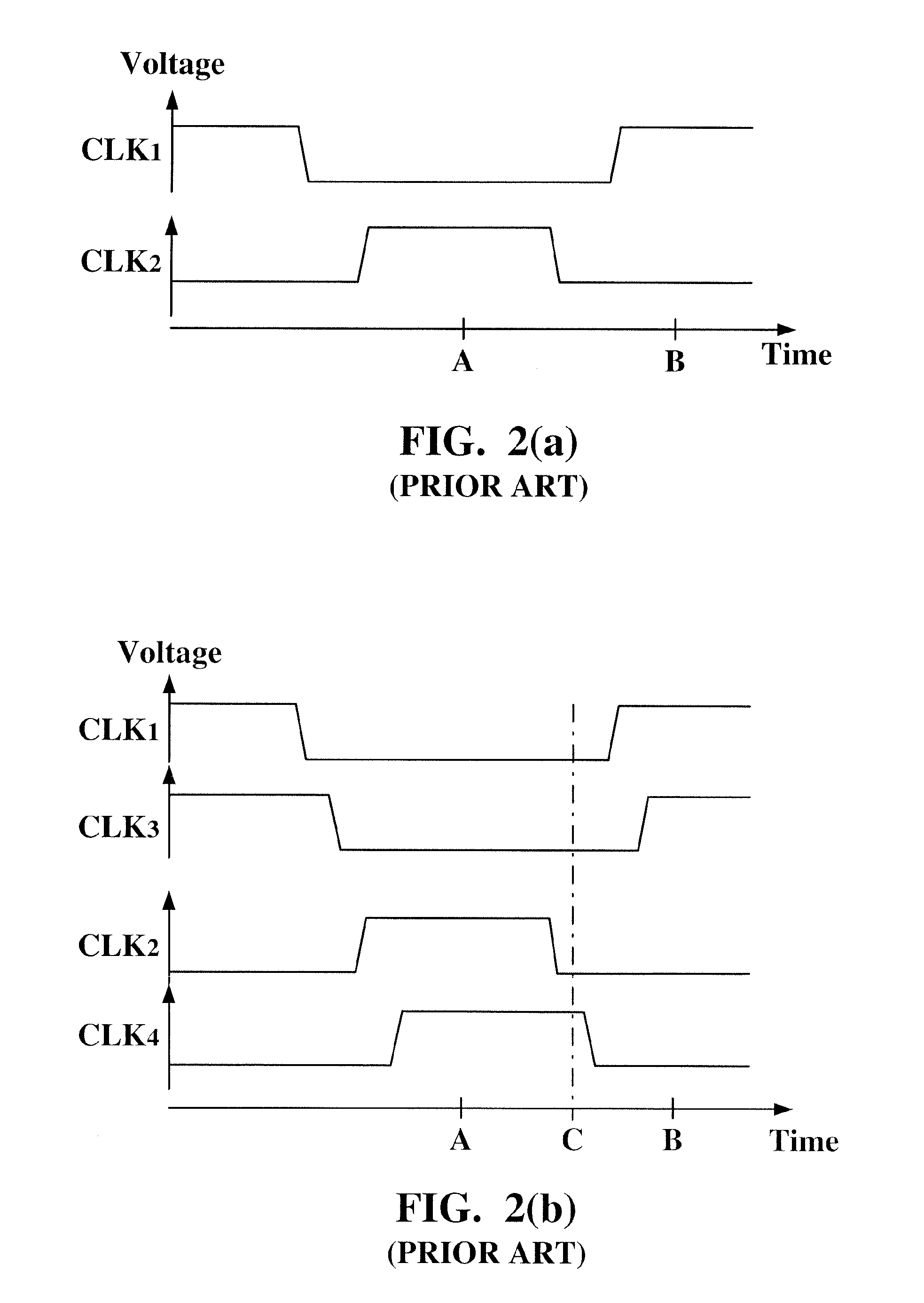
[0042]The charge pump 30 according to the present invention performs charge transferring operations under the control of the conventional clock signals CLK1 and CLK2 shown in FIG. 2(a) so as to achieve the voltage boosting characteristic. For the sake of simplicity, the description of the clock signals CLK1 and CLK2 should be referred to the paragraphs set forth and omitted in the following paragraphs.

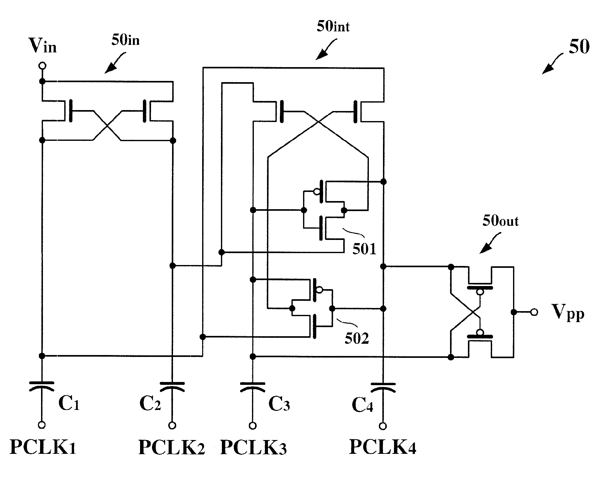
[0043]As clearly seen from comparison of FIG. 1 and FIG. 3(a), the charge pump 30 according to the first embodiment of the present invention is different from the conventional charge pump 10 in that: (1) the intermediate stage 30int of the charge pump 30 is additionally provided with the reverse current preventing circuits 301 and 302, and (2) the output stage 30out is implemented by the PMOS transistors P1 and P2.

[0044]The first reverse current preventing circuit 301 applies a dynamic bias to the control electrode of the transistor N3 for preventing a reverse current from flowing in a...

third embodiment

[0055]Hereinafter is described in detail an operation of the charge pump 40 according to the present invention with reference to the drawings. When the clock signals PCLK1 and PCLK1 are both at the low level and the clock signals PCLK1 and PCLK3 are both at the high level, such as a time interval A shown in FIG. 4(b), the second current electrode of the transistor N1 is at a voltage of Vin, the second current electrode of the transistor N2 is at a voltage of 2*Vin, the second current electrode of the transistor N3 is at a voltage of 2*Vin, the second current electrode of the transistor N4 is at a voltage of 3*Vin. Subsequently, when the latter-stage clock signal PCLK4 makes a transition to the low level earlier in time and the former-stage clock signal PCLK2 still stays at the high level, such as a time interval B shown in FIG. 4(b), the control electrode of the transistor N3 since coupled to the second current electrode of the transistor N4 is pulled downwardly to a voltage of 2*Vi...


PUM


Abstract

First and second clocks are applied to first and second capacitors, respectively. First and second former-stage clocks are applied to first and second former-stage capacitors, respectively. A first switch couples the second former-stage capacitor with the first capacitor. A second switch couples the first former-stage capacitor with the second capacitor. A first reverse current preventing circuit couples a control electrode of the first switch alternately with the second capacitor and the second former-stage capacitor. A second reverse current preventing circuit couples a control electrode of the second switch alternately with the first capacitor and the first former-stage capacitor. Falling edges of the first and second clocks occur earlier than falling edges of the first and second former-stage clocks, respectively. Rising edges of the first and second former-stage clocks occur earlier than rising edges of the first and second clocks, respectively.

Description

BACKGROUND OF INVENTION[0001]1. Field of the Invention[0002]The present invention relates to a charge pump and, more particularly, to a charge pump capable of preventing from reverse current, thereby generating a pumping voltage with high efficiency.[0003]2. Description of the Related Art[0004]FIG. 1 is a detailed circuit diagram showing a conventional charge pump 10. NMOS transistors N1 and N2 have first current electrodes together coupled to a supply voltage source Vin. A control electrode of the NMOS transistor N1 is coupled to a second current electrode of the NMOS transistor N2 while a control electrode of the NMOS transistor N2 is coupled to a second current electrode of the NMOS transistor N1. A capacitor C1 has a first electrode coupled to the second current electrode of the NMOS transistor N1 while a capacitor C2 has a first electrode coupled to the second current electrode of the NMOS transistor N2.[0005]An NMOS transistor N3 has a first current electrode coupled to the se...

Claims


Application Information

Patent Timeline
Patent Type & Authority Patents(United States)
IPC IPC(8): G05F3/02H03L7/00
CPCH02M3/073
Inventor CHEN, TIEN-TZUTZENG, GUANG-NAN
Owner GLOBAL MIXED MODE TECH
Why Eureka
Try Eureka