Transformer with voltage regulating means

a transformer and voltage regulation technology, applied in the direction of power cables, cables, insulated conductors, etc., can solve the problems of large and achieve the effect of reducing the space occupied by the regulating windings

Inactive Publication Date: 2006-02-07
ABB (SCHWEIZ) AG
View PDF766 Cites 44 Cited by
  • Summary
  • Abstract
  • Description
  • Claims
  • Application Information

AI Technical Summary

Benefits of technology

[0009]Irrespectively of whether the regulating windings are incorporated in a power transformer or in a regulation transformer, it is technically and economically favorable to reduce the space occupied by the regulating windings. An objective of the invention is to provide a transformer in which the regulating windings display a compact design. This objective is achieved by a transformer where at least one of the regulating windings at least partly includes a flexible conductor having an electric field containing mechanism.

Problems solved by technology

Depending on the regulating voltage, the space occupied by the regulating windings may be quite large due to insulation requirements.

Method used


Image

  • Transformer with voltage regulating means
  • Transformer with voltage regulating means
  • Transformer with voltage regulating means

Examples


first embodiment

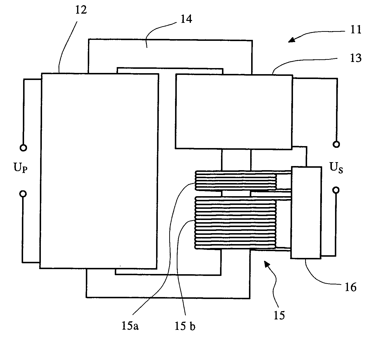
[0017]the invention, a single-phase transformer 11 with voltage regulator for voltage control, is schematically shown in FIG. 1 in order to illustrate the principle of the invention. A primary winding 12 and a secondary winding 13 are wound around a transformer core 14. The regulator includes a regulating winding 15 that is wound around the core 14 and a tap changer 16. The regulating winding 15 is divided into two regulating winding parts 15a, 15b, each being connected to the tap changer 16. The secondary winding 13 is via the tap changer 16 connected in series with the regulating winding 15. The transformer 11 interconnects two electrical systems, one with a voltage level corresponding to the primary voltage UP and one with a voltage level corresponding to the secondary voltage US. By way of the tap changer 16 and the regulating winding parts 15a, 15b, the secondary voltage US can be adjusted in discrete voltage levels and thus the transformer ratio UP / US can be regulated.

[0018]In...

second embodiment

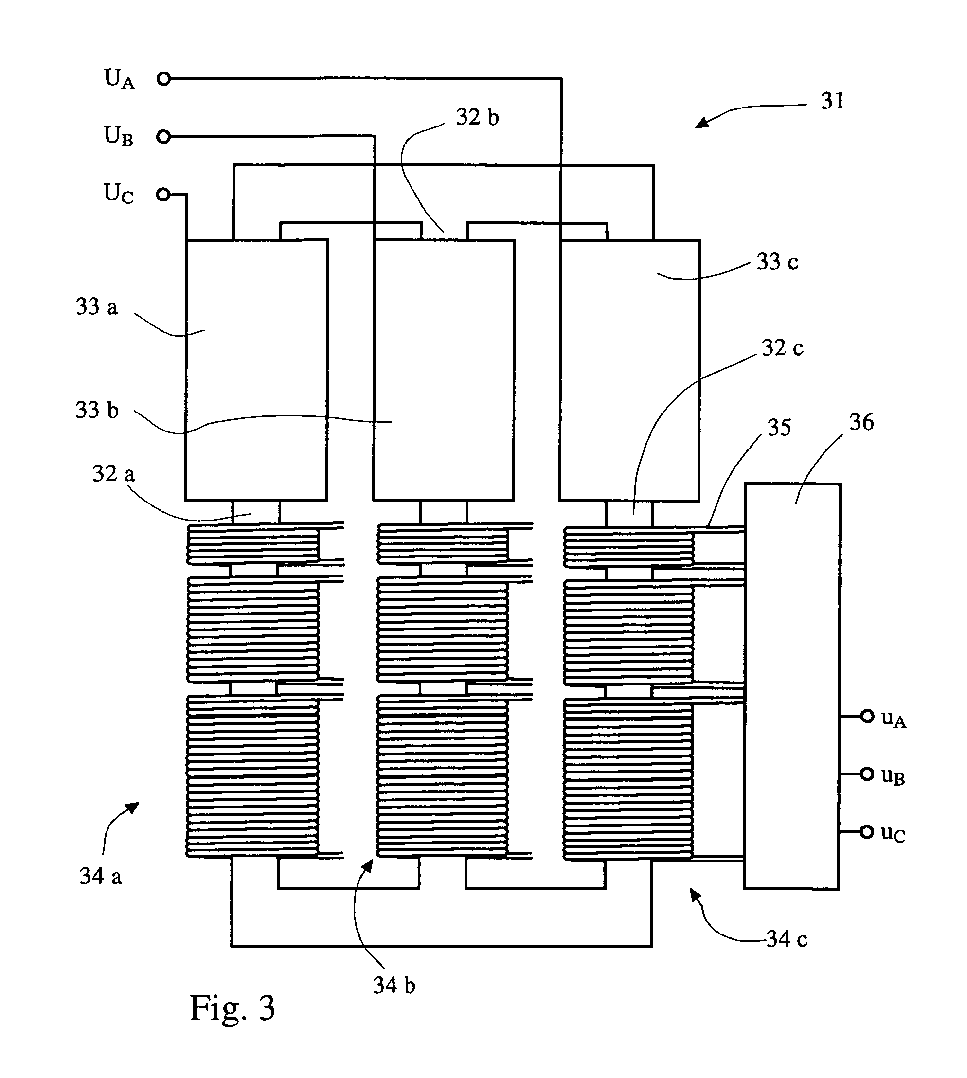
[0020]In FIG. 3 the invention is schematically illustrated. It is a three-phase regulating transformer 31 with a voltage regulator which provides phase angle regulating possibilities between the input and output side of the transformer. The transformer 31 connects a first electrical system with phase voltages UA, UB, UC, to a second electrical system with phase voltages UA, UB, UC. The transformer 31 has three core legs 32a, 32b, 32c made of a magnetizable material. On each core leg, a primary winding 33 and a regulating winding 34 is wound. Normally the windings on each core leg are wound one outside the other.

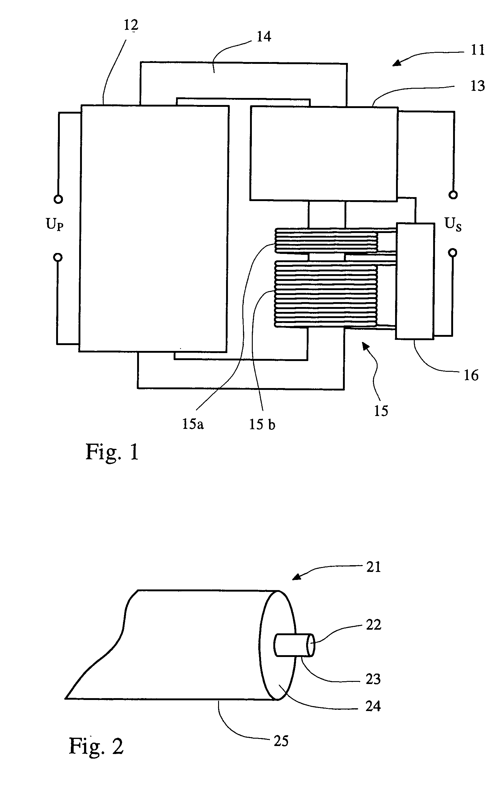
[0021]For clarity reasons however, the windings on each core leg in FIG. 3 are shown one after the other. The primary winding 33 and the regulating winding 34 on each core leg 32 are made of a flexible conductor with an electric field containing mechanism 35. The conductor 35 ay for example be a cable of the sort described in FIG. 2. The regulating windings 34 are divided int...


PUM

PropertyMeasurementUnit
transmission voltagesaaaaaaaaaa
voltageaaaaaaaaaa

Abstract

A power or regulating transformer with voltage regulator includes regulating windings made of a flexible conductor having an electric field containing mechanism that forces the electric field due to the current in the winding to be contained within the flexible conductor. Since virtually no electric field is to be found outside the flexible conductor of the regulating winding, the regulating winding may be formed without having to consider the electric field distribution, thus providing for a transformer with a favorable regulating winding design.

Description

BACKGROUND OF THE INVENTION[0001]1. Field of the Invention[0002]The present invention relates to a power or regulating transformer, with a voltage regulator, in a power generation, transmission or distribution system with a rated power ranging from a few hundred kVA up to more than 1000 MVA and with a rated voltage ranging from 3–4 kV and up to very high transmission voltages, 400 kV to 800 kV or higher.[0003]More specifically the invention relates to regulating windings in the power or regulating transformer.[0004]2. Discussion of the Background[0005]The primary task of a power transformer is to act as an electric “gear box”, allowing electric energy to flow from one electrical system to another. The electrical systems interconnected with a transformer usually have different voltages but the same frequency. The power transformer, in its simplest form, has only two types of windings, a primary winding and a secondary winding. The transformation ratio is thereby fixed, that is, not p...

Claims


Application Information

Patent Timeline
Patent Type & Authority Patents(United States)
IPC IPC(8): H01F27/30H01F27/28H01F27/32H01F29/02H01F29/14H01F30/00H01F38/04
CPCH01F29/14H01F38/04H02K2203/15H01F2029/143
Inventor FROMM, UDOHOLMBERG, PARJAKSTS, ALBERTLEIJON, MATSSASSE, CHRISTIANSCHUTTE, THORSTEN
Owner ABB (SCHWEIZ) AG
Why Eureka
Try Eureka