Electronic endoscope forming still image by double-speed reading

a technology of electronic endoscope and still image, which is applied in the field of electronic endoscope, can solve the problems of complicated drive circuit itself, complicated drive control, and complicated configuration

Inactive Publication Date: 2006-02-07
FUJI PHOTO OPTICAL CO LTD
View PDF6 Cites 53 Cited by
  • Summary
  • Abstract
  • Description
  • Claims
  • Application Information

AI Technical Summary

Benefits of technology

[0012]According to the above-described configuration, the image pickup signal is read based on the first reference signal (clock signal) at a standard speed of, for example, approximately 14 MHz, and a moving image is formed in this way. When a still image switch is operated, the image pickup signal is read based on the second reference signal (clock signal) at a double-speed of approximately 28 MHz, this signal is subjected to image processing and then written i

Problems solved by technology

However, the conventional electronic endoscope needs to include the light shielding shutter 4 to shield light of the lamp 2 and the shutter drive circuit 7 including a motor to drive this shutter 4 as shown in FIG. 6 to create the above-described light shielding period, which involves a problem of complicating the configuration.
Furthermore, because of t

Method used


Image

  • Electronic endoscope forming still image by double-speed reading
  • Electronic endoscope forming still image by double-speed reading
  • Electronic endoscope forming still image by double-speed reading

Examples


Embodiment Construction

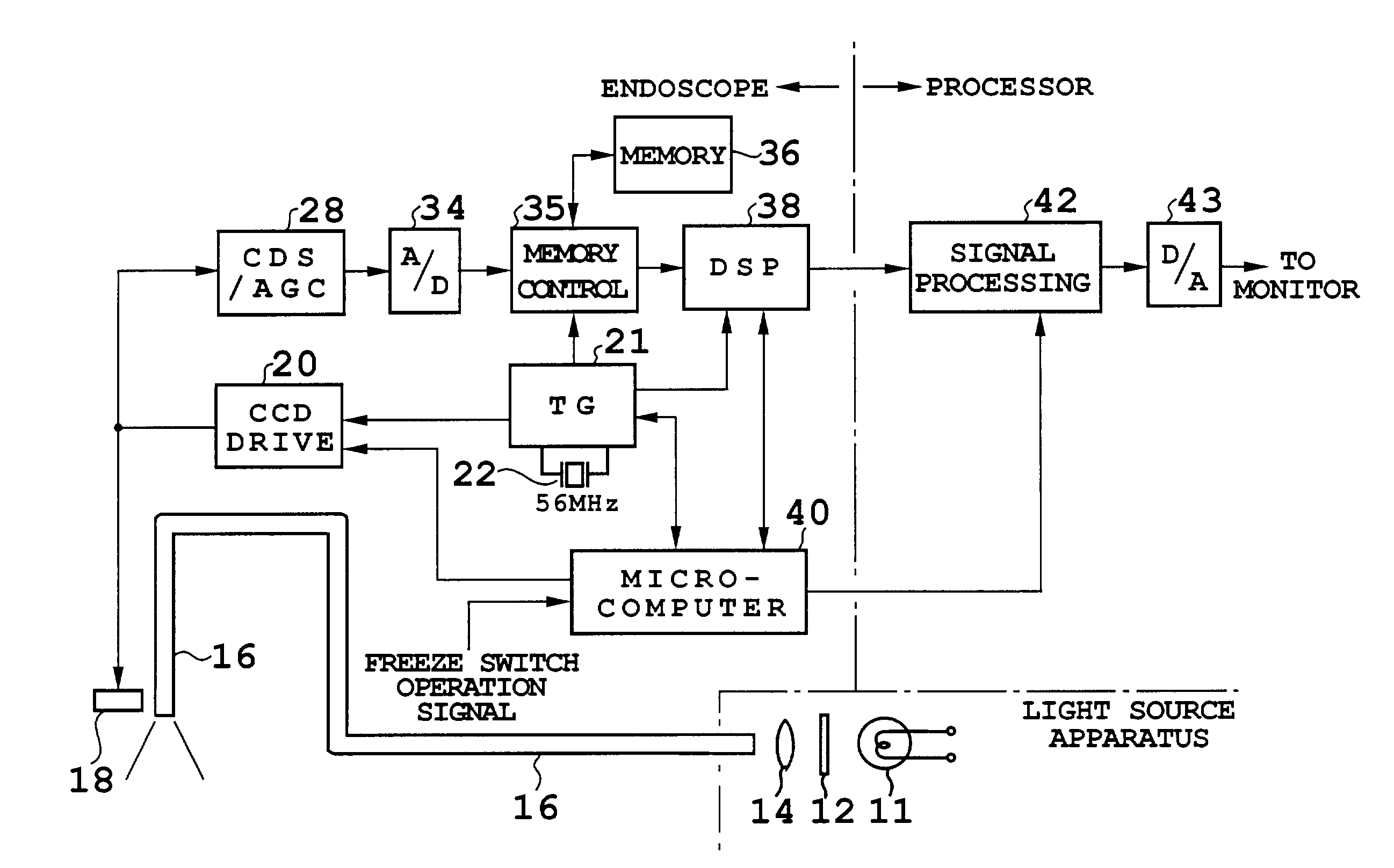
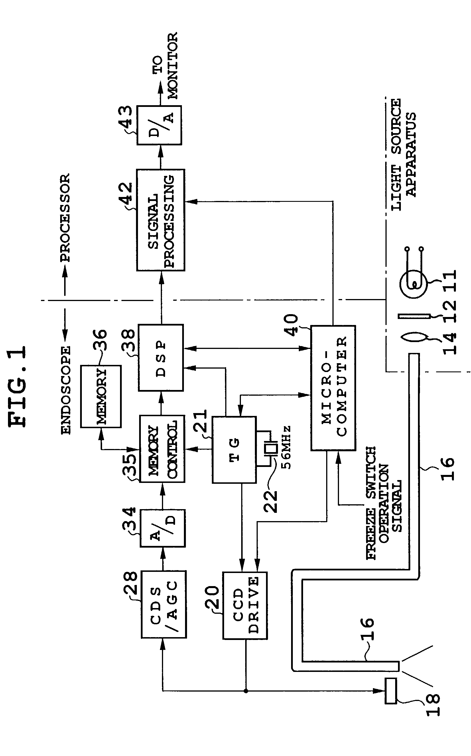
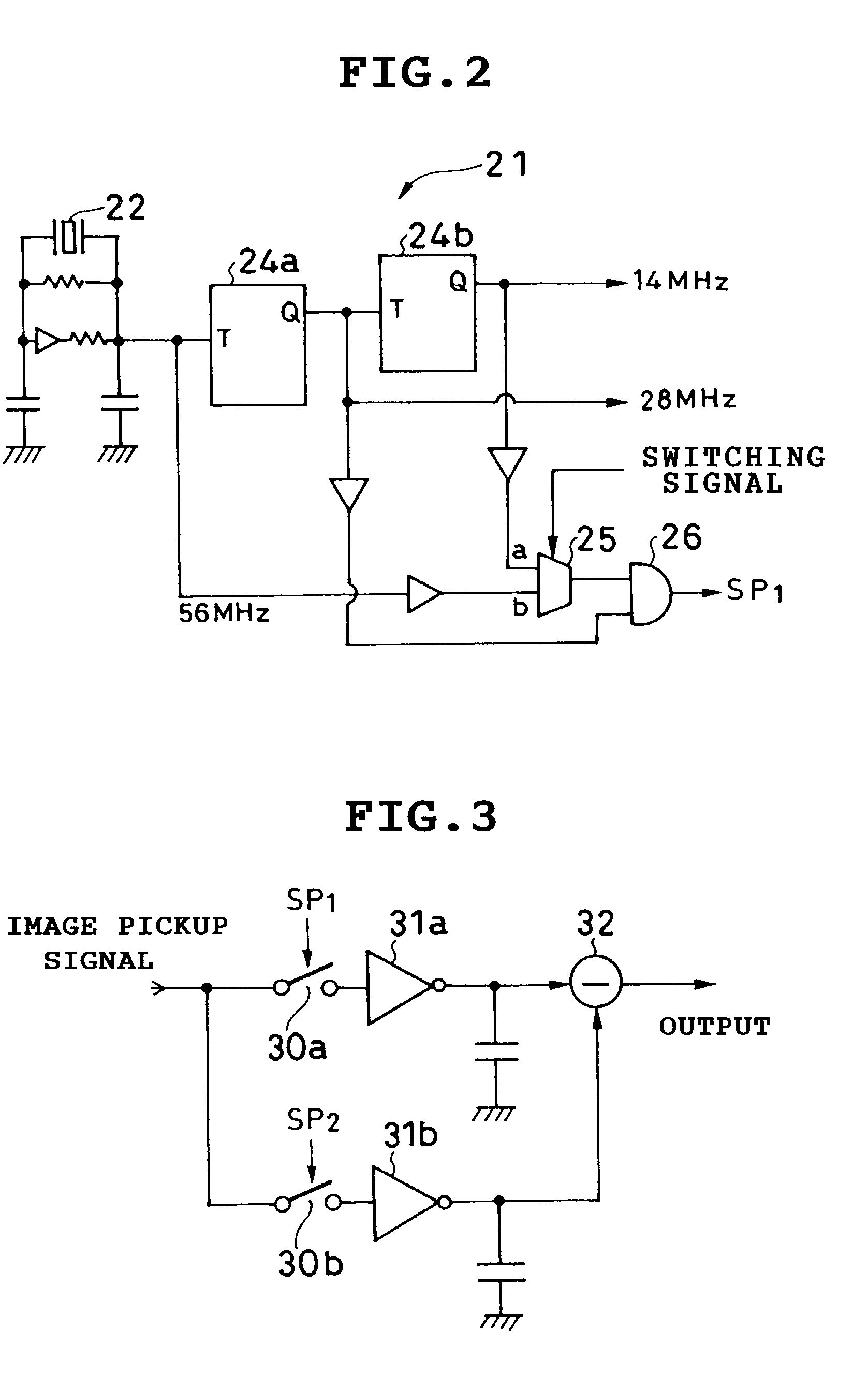
[0020]FIG. 1 to FIG. 3 show a configuration of an electronic endoscope according to an embodiment of the present invention and this electronic endoscope is provided with a scope, a processor apparatus and a light source apparatus, etc. In this FIG. 1, the light source apparatus is provided with a lamp 11 such as xenon lamp, a light quantity adjuster 12, a condensing lens 14 and light from this condensing lens 14 is supplied to a light guide 16. As shown in the drawing, there is neither light shielding plate nor light shielding plate drive circuit to shield light from the lamp 11.

[0021]The above described light guide 16 extends from the light source apparatus to the tip of the scope and a CCD (image pickup element) 18 to capture an image of an object under observation is provided at the tip of this scope via an objective optical system. This CCD 18 is connected to a CCD drive circuit 20 that outputs a sweeping pulse (SUB pulse), a reading pulse and a horizontal transfer pulse, etc. t...


PUM


Abstract

To provide a timing generator which generates a first reference signal at a standard speed of approximately 14 MHz and a second reference signal operating at approximately 28 MHz which is double the standard speed and forms a moving image based on the first reference signal, reads, when a freeze switch is operated, an image pickup signal based on the second reference signal operating at the double speed and writes this signal into the memory 36 at the same speed. Then, by reading this still image signal from the memory at the standard speed, the still image is displayed on the monitor. Thereby, the need for setting a conventional light shielding period can be eliminated.

Description

BACKGROUND OF THE INVENTION[0001]This application claims the priority of Japanese Patent Application No. 2001-290538 filed on Sep. 25, 2001 which is incorporated herein by reference.[0002]1. Field of the Invention[0003]The present invention relates to an electronic endoscope, and more particularly, to signal processing control of an electronic endoscope which reads signals of all pixels of a still image obtained by exposure within a 1 vertical scanning period and forms a 1-frame image.[0004]2. Description of the Related Art[0005]In an electronic endoscope, light from a light source lamp is guided through a light guide to a tip of a scope and the light is irradiated from this scope tip onto an object under observation and an image of this object is taken by an image pickup element such as a CCD (Charge Coupled Device) via an objective optical system. This CCD reads signals (charges) stored every 1-field period one by one and forms moving images. On the other hand, when a still image ...

Claims


Application Information

Patent Timeline
IPC IPC(8): H04N7/18A62B1/04H04N9/47A61B1/04H04N5/225H04N5/335H04N5/341H04N5/353H04N5/372H04N5/376
CPCH04N7/18H04N2005/2255H04N23/555
Inventor ABE, KAZUNORIOKADA, FUJIO
Owner FUJI PHOTO OPTICAL CO LTD
Why Eureka
Try Eureka