PWM controller for synchronous rectifier of flyback power converter

a technology of synchronous rectifier and flyback power converter, which is applied in the direction of power conversion system, dc-dc conversion, climate sustainability, etc., can solve problems such as increasing complexity

Active Publication Date: 2006-02-07
SEMICON COMPONENTS IND LLC
View PDF1 Cites 95 Cited by
  • Summary
  • Abstract
  • Description
  • Claims
  • Application Information

AI Technical Summary

Problems solved by technology

Furthermore, in the above approaches, the transformer requires an additional auxiliary winding to generate a driving signal to achieve synchronous rectification; and thus increases the complexity thereof.

Method used


Image

  • PWM controller for synchronous rectifier of flyback power converter
  • PWM controller for synchronous rectifier of flyback power converter
  • PWM controller for synchronous rectifier of flyback power converter

Examples


Embodiment Construction

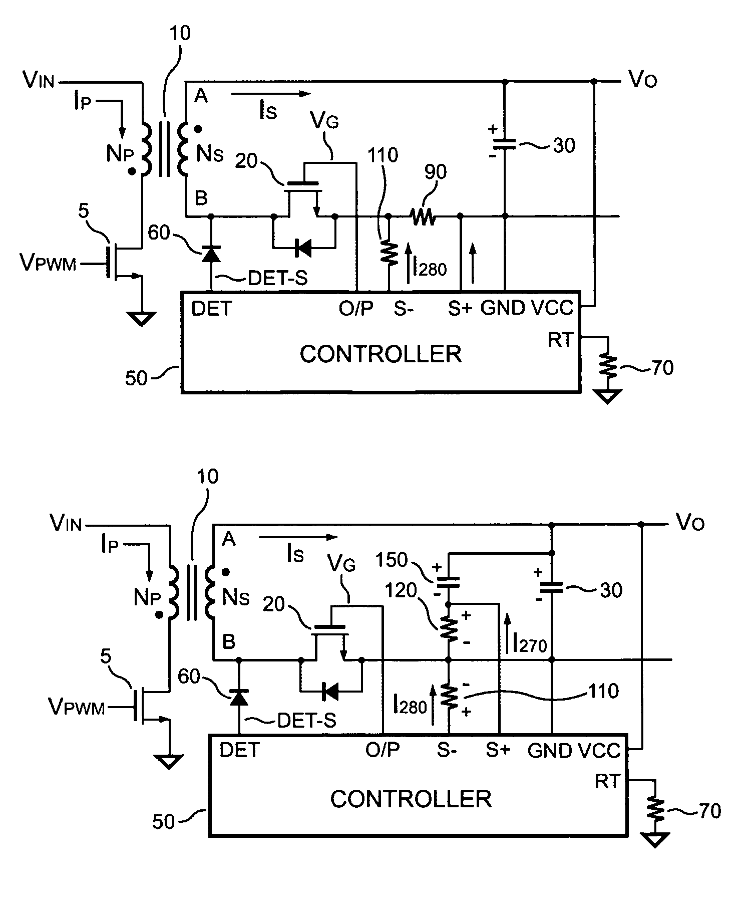
[0027]Referring to FIG. 4, it illustrates a Synchronous Rectifier PWM (SR-PWM) controller 50 for a flyback power converter according to one embodiment of the present invention. In FIG. 4, the flyback power converter includes a transformer 10 having a primary winding NP coupled to a primary circuit and a secondary winding NS coupled to a secondary circuit. In the primary circuit, the primary winding NP is coupled between an input voltage source VIN and a switching device 5. The secondary circuit includes a MOSFET 20, an output capacitor 30, and the SR-PWM controller 50. A drain of the MOSFET 20 is connected to a terminal B of the secondary winding NS. The output capacitor 30 is connected between a terminal A of the secondary winding NS and an output terminal of the secondary circuit. The SR-PWM controller 50 is coupled to the MOSFET 20. A resistor 90 serves as a current sensor, which is coupled between a source of the MOSFET 20 and a negative terminal of the output capacitor 30. The ...


PUM


Abstract

A synchronous rectifier PWM (SR-PWM) controller controls a MOSFET in response to the value of a secondary current and the status of a synchronous signal for both discontinuous and continuous operation mode. The secondary current is generated in a secondary circuit and is detected by two threshold-detection terminals of the SR-PWM controller. The SR-PWM controller produces the synchronous signal by detecting a switching signal of the transformer via a detection terminal of the SR-PWM controller. Furthermore, a delay-time is inserted after the MOSFET is turned off and before the next switching cycle starts to ensure a proper operation of the MOSFET. In one embodiment, an equivalent series resistance (ESR) of an output capacitor can be used as a sensor to detect the secondary current. Therefore, no additional current sensor is required.

Description

BACKGROUND OF THE INVENTION[0001]1. Filed of the Invention[0002]The present invention relates to a pulse width modulation (PWM) controller of flyback power converter, and more particularly, to a synchronous rectifier PWM controller (SR-PWM) for a flyback power converter to improve efficiency of power conversion.[0003]2. Description of Related Art[0004]Power converters have been frequently used for converting an unregulated power source to a constant voltage source. Among various power converters, flyback topology is the most common one. A transformer having a primary winding and a secondary winding is the major part of a flyback power converter. In application, the primary winding is connected to the unregulated power source, preferably a DC voltage source, and a switching device is connected to the primary winding to switch on and off the connection between the unregulated power source and the primary winding. A rectifying diode is typically connected to the secondary winding for r...

Claims


Application Information

Patent Timeline
Patent Type & Authority Patents(United States)
IPC IPC(8): H02M3/335
CPCH02M3/33592Y02B70/1475Y02B70/10
Inventor YANG, TA-YUNGKUO, JUN-JIECHEN, TSO MIN
Owner SEMICON COMPONENTS IND LLC
Why Eureka
Try Eureka