
Device for optical signal transmission between two units movable relative to each other

a technology of optical signal transmission and light guide, which is applied in the direction of fiber transmission, electromagnetic transmission, transmission, etc., can solve the problem that the transmission system is substantially insensitive to the contamination of the light guide, and achieve the effect of not sensitive to mechanical tolerances

Inactive Publication Date: 2006-02-07
SCHLEIFRING & APPBAU
View PDF17 Cites 5 Cited by
  • Summary
  • Abstract
  • Description
  • Claims
  • Application Information

AI Technical Summary

Benefits of technology

"The invention is a system for transmitting optical data using a light guide. The system is designed to be economical and insensitive to mechanical tolerances. It is also resistant to contamination of the light guide. The system includes an optical transmitter, a light guide, and an optical receiver. The light guide has a reflecting surface or a transparent material surrounded by a lower refractive index medium. The light guide also has a light-guiding medium that can change its transmission characteristics based on external electromagnetic fields or radiation. A probe is placed along the light guide to apply electric, magnetic, or radiation fields to change the transmission characteristics of the light guide. This allows for the transmission of information through the light guide with changing characteristics."

Problems solved by technology

Furthermore, the transmission system is to be substantially insensitive to contamination of the light guide.

Method used


Image

  • Device for optical signal transmission between two units movable relative to each other
  • Device for optical signal transmission between two units movable relative to each other
  • Device for optical signal transmission between two units movable relative to each other

Examples


Embodiment Construction

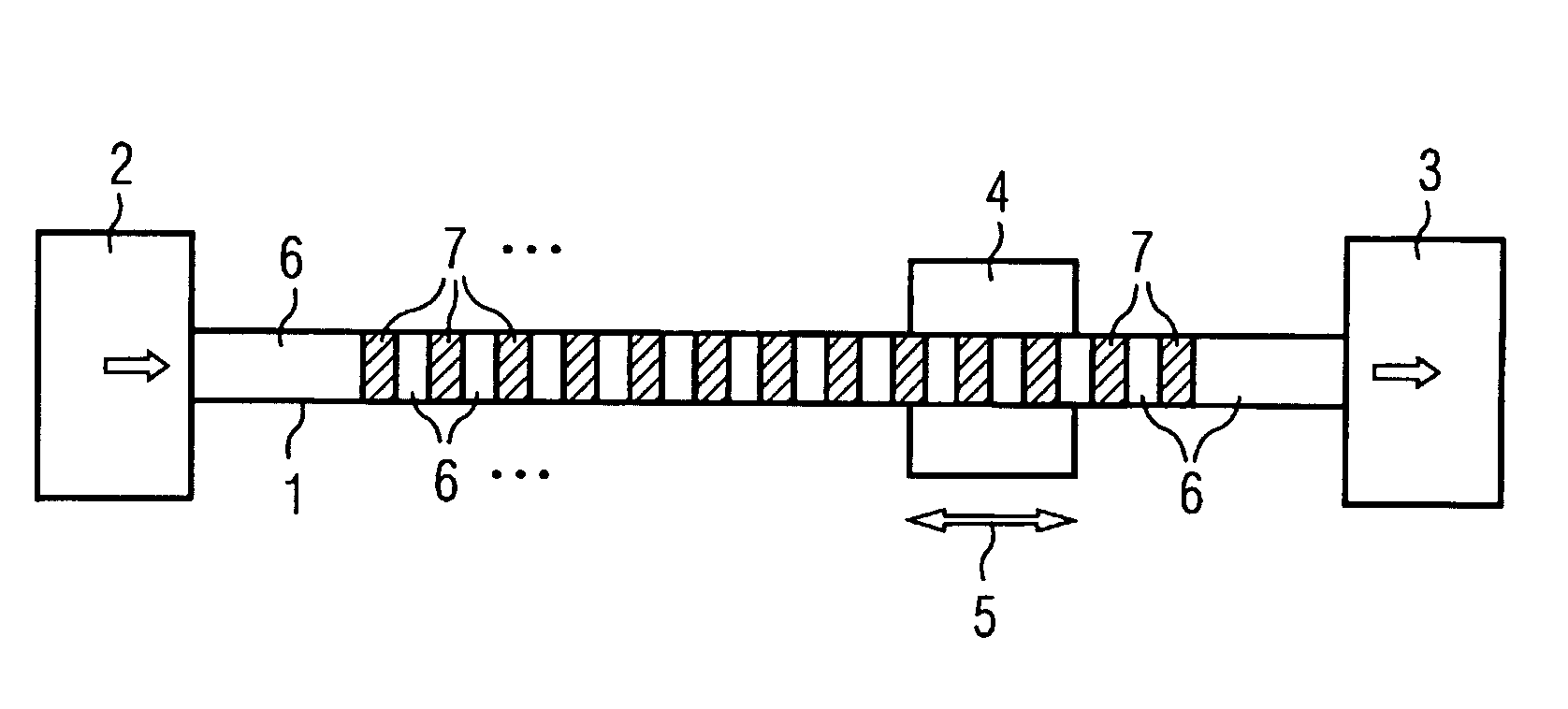
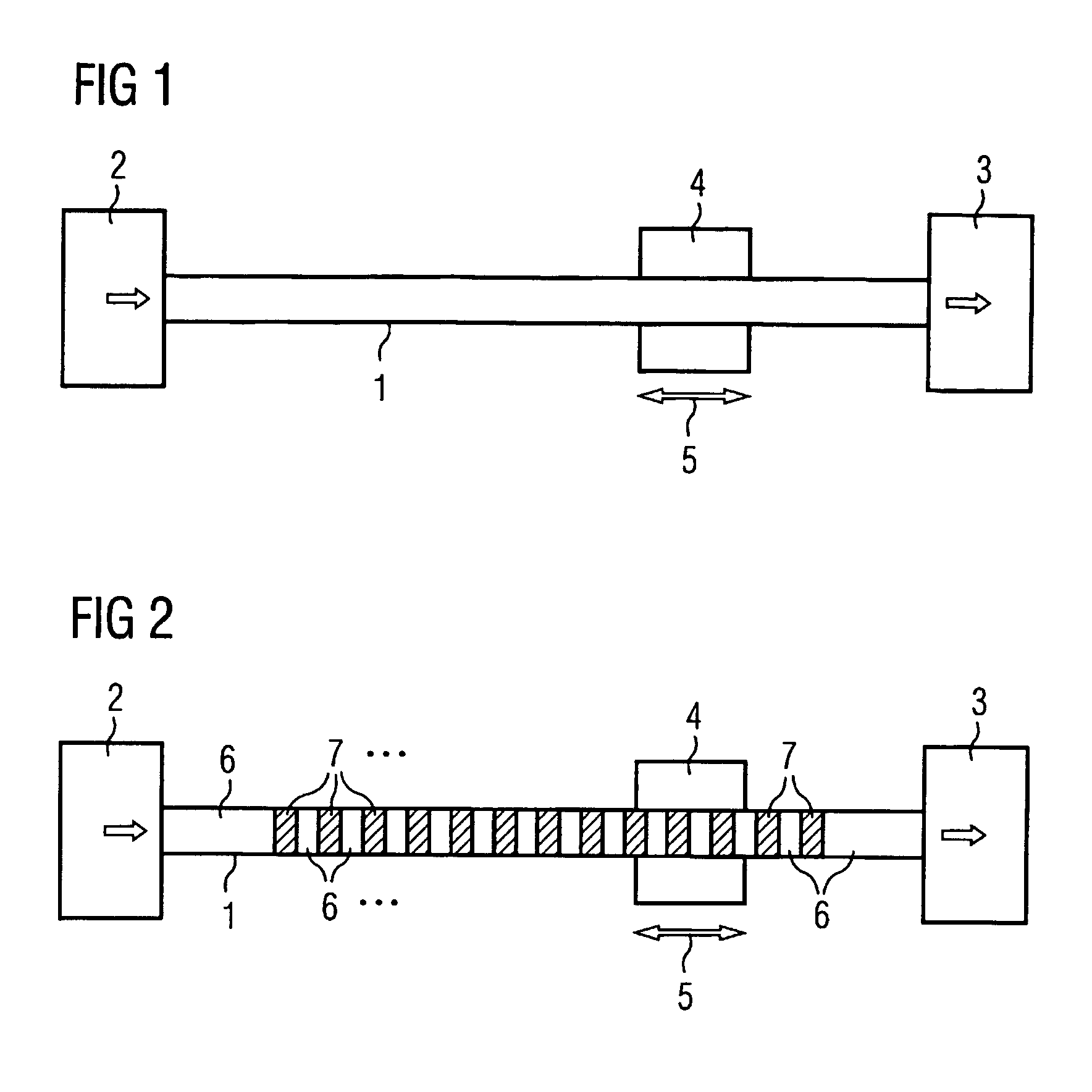
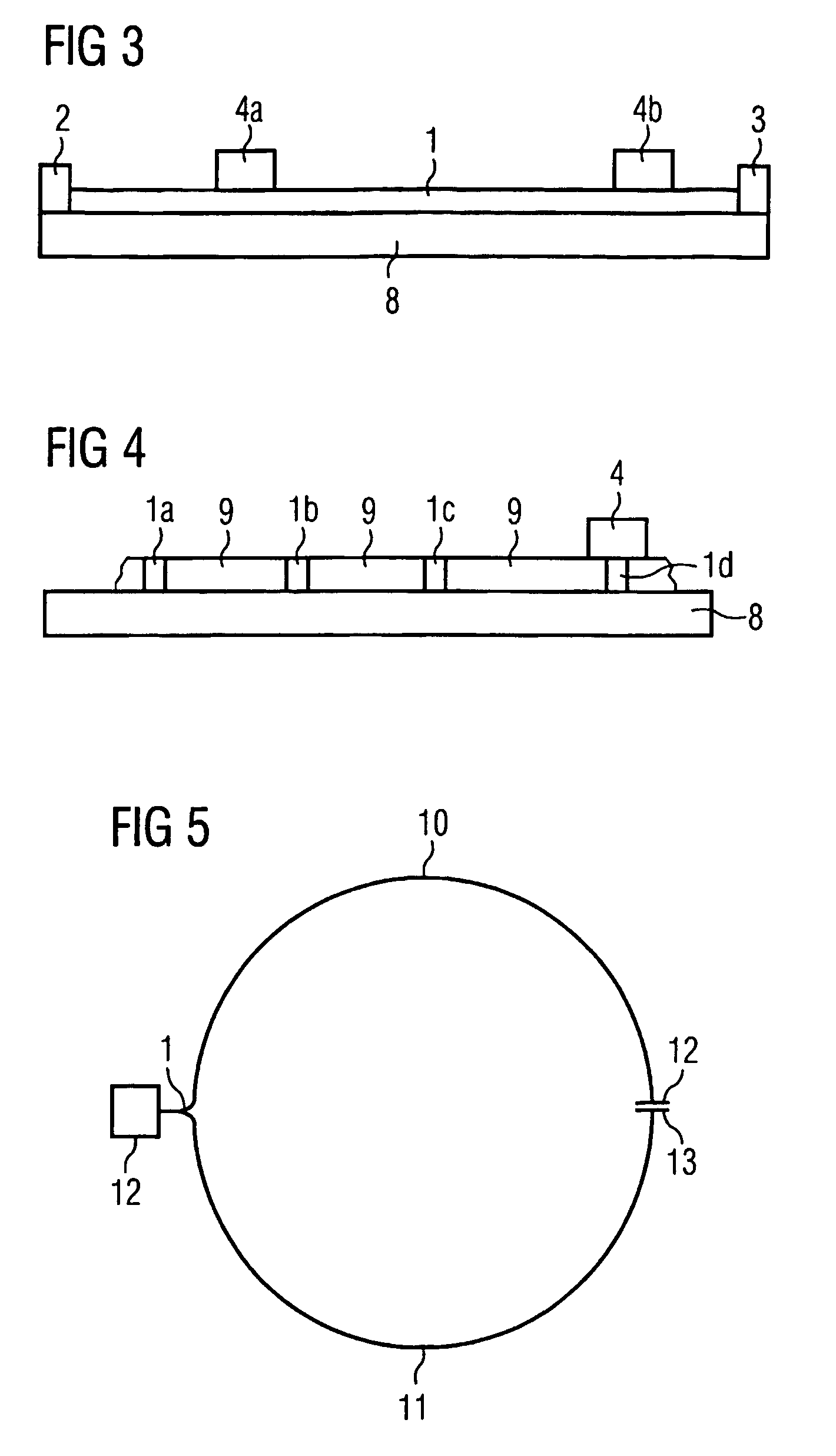
[0023]The transmission device in accordance with the invention comprises a light guide that is connected to an optical transmitter and an optical receiver, so that the receiver can receive the light emitted by the transmitter. The light guide may be, for example, a planar light guide, or a light-guiding fiber, for example a plastics fiber or glass fiber, or a hose filled with gas or liquid. In the case of light-guiding fibers, the transmitter is disposed preferably at the first end, and the receiver at the second end.

[0024]For transmitting information, the light guide comprises at least one light guiding medium in the region between the transmitter and the receiver, which exhibits at least one optical effect that can be changed by external electrical, magnetic or electromagnetic fields, or by radiation. This makes it possible for the light fed in from the transmitter to be changed or modulated by means of changes of the optical effect. Of course, in the case of a plurality of coupli...


PUM

PropertyMeasurementUnit
circumferential speedaaaaaaaaaa
transparentaaaaaaaaaa
refractive indexaaaaaaaaaa

Abstract

A device for transmitting information between at least two units mobile relative to each other comprises a light guide having a light-guiding medium, the optical properties of which can be changed by external electromagnetic fields. The light guided in this light guide is modulated by electromagnetic fields emitted by a movable probe.

Description

CROSS REFERENCE TO RELATED APPLICATIONS[0001]This application is a continuation of pending International Application PCT / DE03 / 01536 filed May 13, 2003, which designates the United States and claims priority from pending German Applications DE 102 23 834 filed May 28, 2002 and 102 40 228 filed 28 Aug. 2002.BACKGROUND OF THE INVENTION[0002]1. Field of the Invention[0003]The invention relates to a device for transmitting information by means of light guides, in which a transmitter and / or a receiver are adapted to be moved or differently positioned along a light guide. Similarly, however, the transmitter and the receiver may be disposed at given fixed positions.[0004]Devices of this kind having a linear configuration are employed for example in crane or other conveyor systems for data transmission between a movable crane and a stationary control unit. Another field of application of these data transmission systems having a circular configuration is that of transmission between parts tha...

Claims


Application Information

Patent Timeline
Patent Type & Authority Patents(United States)
IPC IPC(8): G02B6/00G02F1/01G02F1/035G02F1/09H04B10/00
CPCG02F1/011H04B10/22G02F1/0115G02F1/09G02F1/035H04B10/25H04B10/801
Inventor SCHILLING, HARRY
Owner SCHLEIFRING & APPBAU
Learn More