Hermaphrodite connector

Inactive Publication Date: 2006-02-14
INOVA
View PDF4 Cites 22 Cited by
  • Summary
  • Abstract
  • Description
  • Claims
  • Application Information

AI Technical Summary

Benefits of technology

[0035]The present invention addresses the above-noted deficiencies and provides a seismic cable coupling with

Problems solved by technology

Multi-component sensing, however, has not been economically viable in the past due to the added cost of the recording system and implementation problems with multi-component analog sensors.
The deployment of miles of cable over varying terrain requires significant equipment and labor, often in harsh environments.
Connectors in the typical seismic system have long been a source of frustration in the field.
Harsh environmental conditions, debris and complexity all contribute to difficulty in making up the system and in disassembling the system.
Furthermore, seismic cables are often connected and disconnected during times of freezing rain and/or snow.
The typical connector often seizes under harsh conditions making connections and disconnections difficult if not impossible.
When the connector is difficult to disconnect due to debris, freezing or misalignment, the operator is often tempted to pull on the cables.
Pulling cables rather t

Method used


Image

  • Hermaphrodite connector
  • Hermaphrodite connector
  • Hermaphrodite connector

Examples


Embodiment Construction

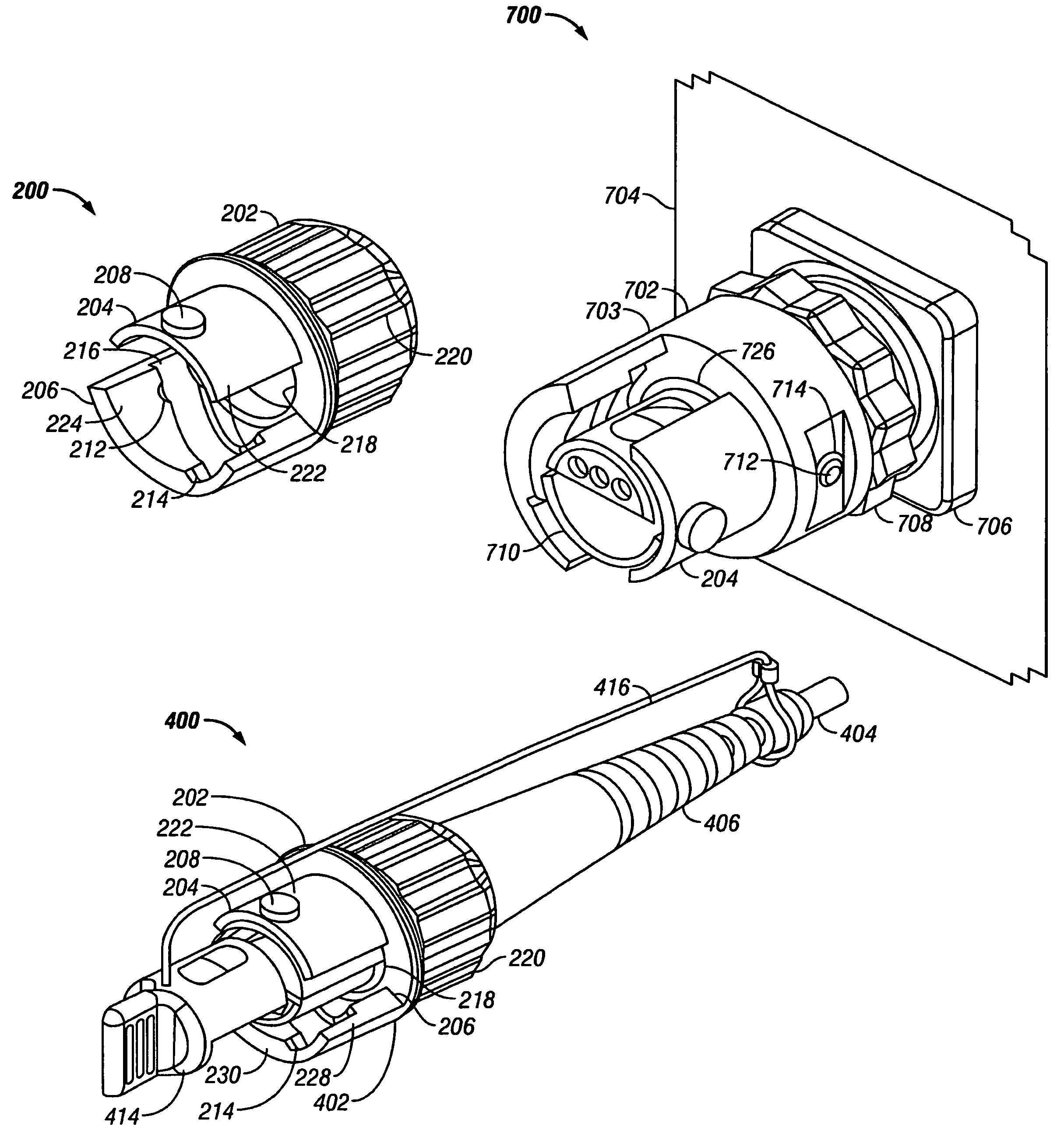
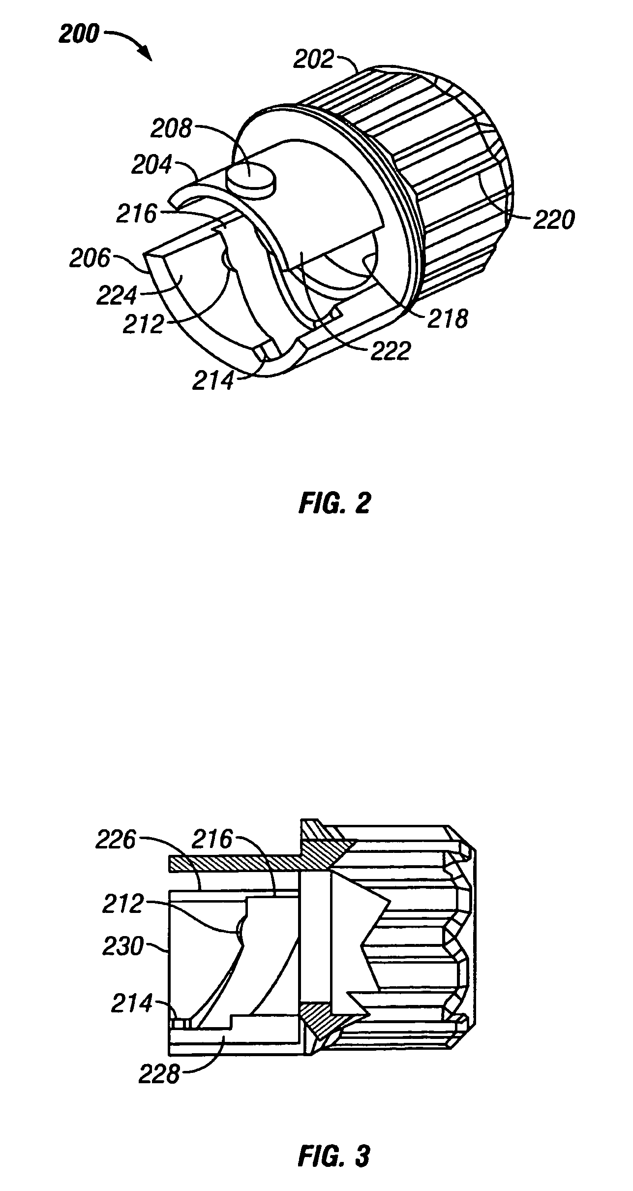
[0052]FIG. 2 is a perspective view of a connector coupling ring or lock ring 200 according to the present invention, and FIG. 3 is a partial cross section of the connector lock ring of FIG. 2. The terms coupling ring and lock ring are used interchangeably herein. The lock ring 200 includes a ring body 202 having a substantially annular cross section to provide an axial through bore 218.

[0053]In one embodiment, the ring body 202 includes longitudinal ribs 220 for better gripping.

[0054]A male longitudinal projection 204 extends from the ring body 202. The male longitudinal projection has an outer curved surface 222. A raised stud 208 extends from the outer curved surface 222 and outwardly with respect to a center axis of the lock ring 200.

[0055]A female longitudinal projection 206 extends from the ring body 202 substantially opposite the male longitudinal projection 204. The female longitudinal projection has an inner curved surface 224 and has a groove210 formed therein. The groove 2...


PUM


Abstract

A seismic cable coupling comprising connector body, a coupling ring is rotatably mounted on the connector body. The coupling ring includes a ring body having a first longitudinal projection and a second longitudinal projection, the first longitudinal projection having an interior surface including a first angled groove, the second longitudinal projection having an exterior surface including a first raised stud. The coupling ring is a hermaphrodite coupling ring that mates with a coupling ring having a substantially identical ring body.

Description

BACKGROUND OF THE INVENTION[0001]1. Field of the Invention[0002]This invention relates generally to apparatus and methods used for seismic surveying, and more particularly to a cable connector and method for assembling a seismic survey system.[0003]2. Description of the Related Art[0004]Seismic surveys are conducted by deploying a large array of seismic sensors over a surface portion of the earth. Typically, these arrays cover 50 square miles and may include 2000 to 5000 seismic sensors. An energy source (buried dynamite for example) is discharged within the array and the resulting shock wave is an acoustic wave that propagates through the subsurface structures of the earth. A portion of the wave is reflected at underground discontinuities, such as oil and gas reservoirs. These reflections are then sensed at the surface by the sensor array and recorded. Such sensing and recording are referred to herein as seismic data acquisition, which might also be performed in a passive mode with...

Claims


Application Information

Patent Timeline
IPC IPC(8): H01R13/62H01R13/213H01R13/28H01R25/00
CPCH01R13/623H01R23/27H01R2201/14H01R24/84
Inventor WOOD, RICHARDDEKKERS, LEO M.
Owner INOVA
Why Eureka
Try Eureka