High strength and ultra-efficient oil coalescer

a coalescer and high strength technology, applied in the field of ultra-efficient filters, separators, coalescers, can solve the problems of disintegration of coalescing elements, special problems in aircraft environments, temperature and gas velocity limitations that are typically found, etc., and achieve the effect of reducing its velocity

Inactive Publication Date: 2006-02-14
HONEYWELL INT INC
View PDF20 Cites 13 Cited by
  • Summary
  • Abstract
  • Description
  • Claims
  • Application Information

AI Technical Summary

Benefits of technology

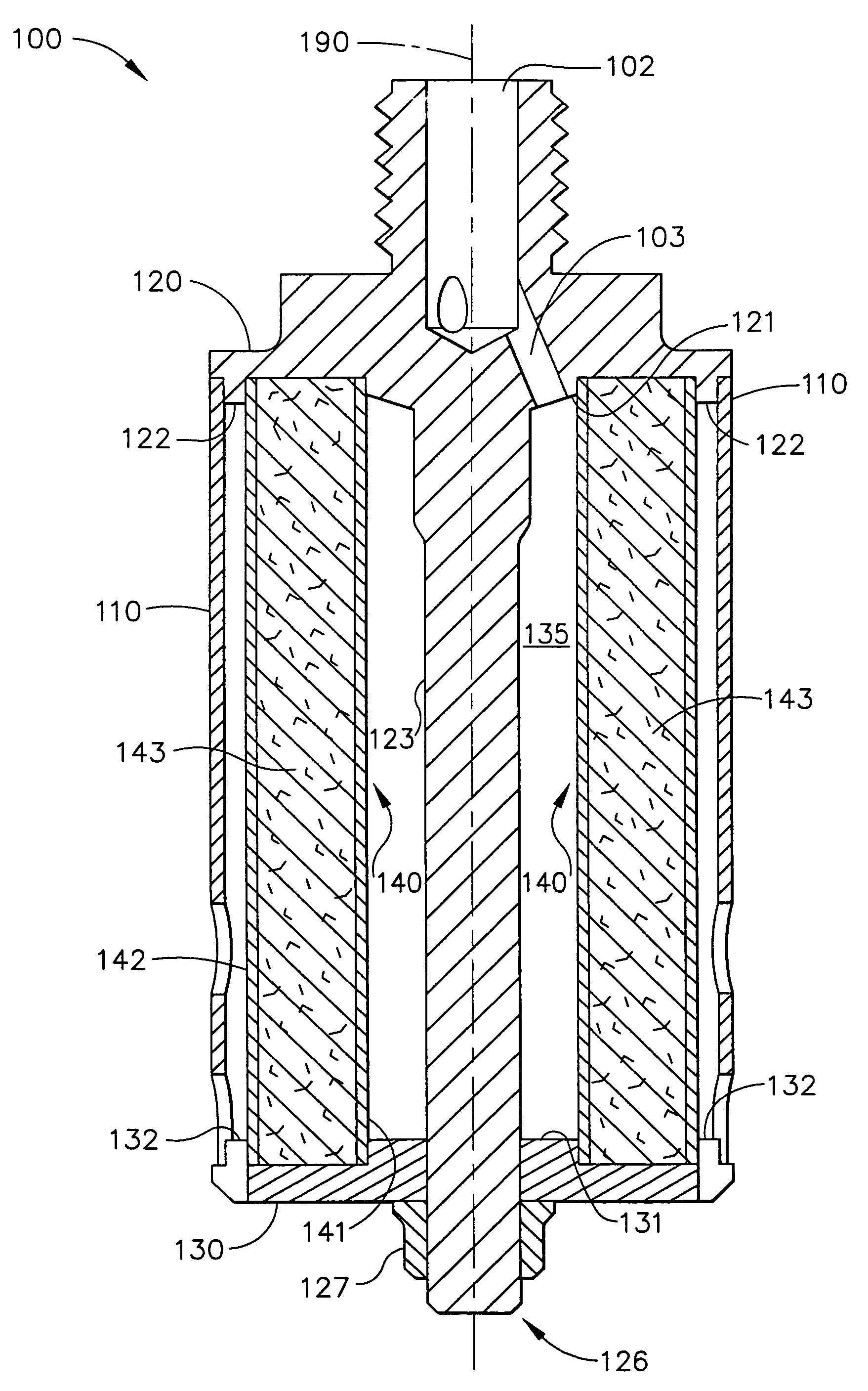
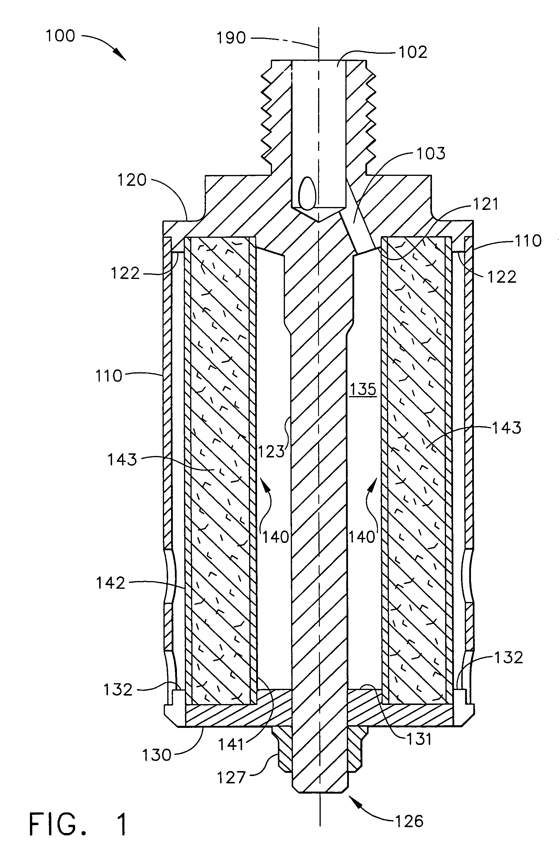
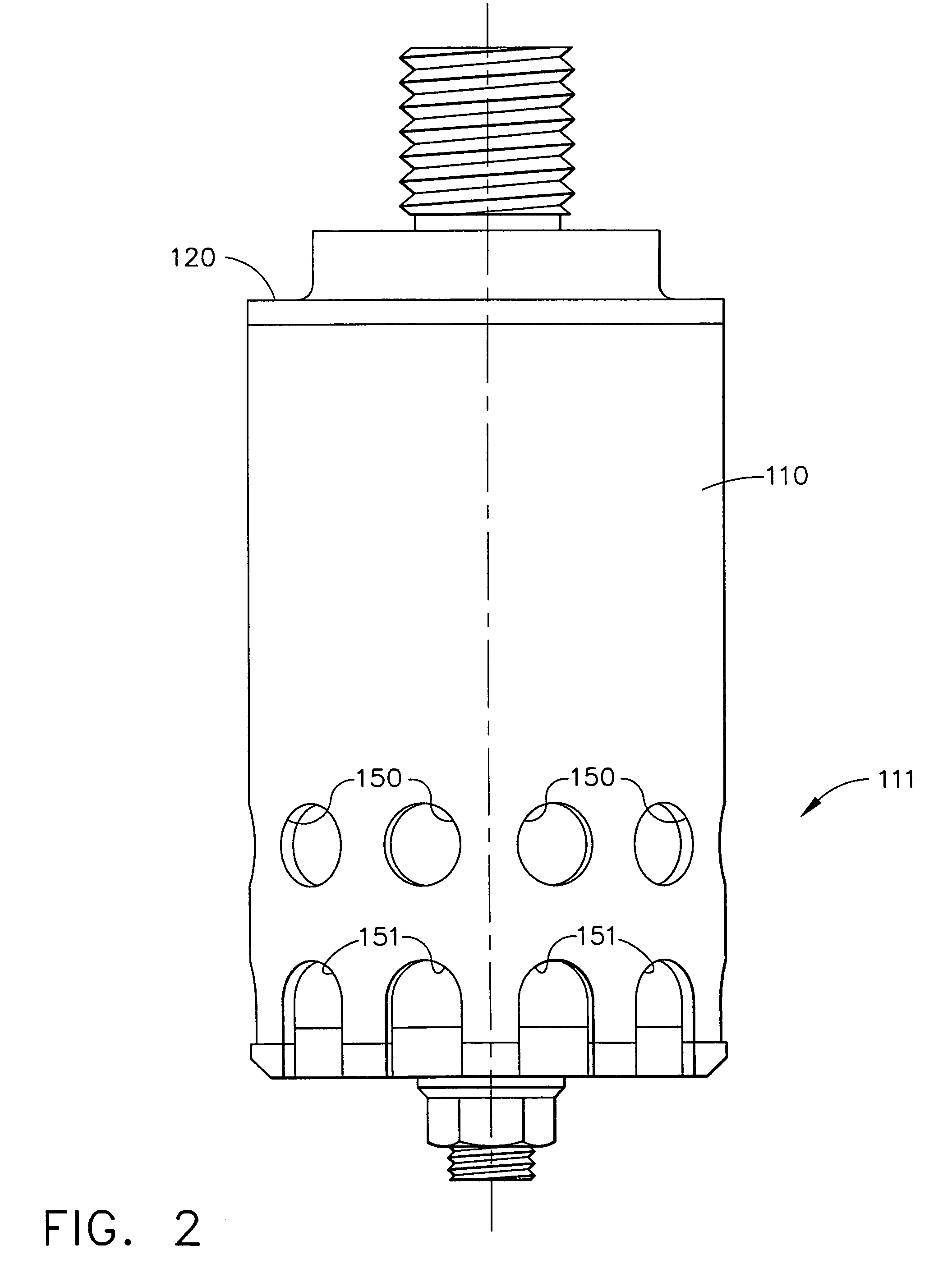
[0012]In another aspect of the present invention, an oil coalescer is provided for removing entrained oils from a high velocity, high temperature gas stream. The inventive oil coalescer comprises a cylindrical coalescing element of compacted high temperature polyamide fibers held in a compacted state by a support structure comprised of a cylindrical, concentric inner and outer fiber-metal sleeves enclosing the coalescing element therebetween. The coalescing element with its support structure is encased by a cylindrical shell, a top cap, and a bottom cap. The cylindrical shell has holes along its lower periphery to allow the gas stream to escape the coalescer without entraining oils that have already been removed, and the bottom cap has holes permitting coalesced oil to drain from the oil coalescer. The oil coalescer also features a diverging channel directing the gas stream through an orifice in the top cap into the inner area, and thereby reducing its velocity by means of adiabatic expansion.

Problems solved by technology

Aircraft environments present a special set of problems for such oil coalescers.
Its temperature and gas velocity limitations are those typically found in trucks and not in aircraft environments, and more specifically, in aircraft piston compressors.
Such oil coalescers have been shown in testing to be unable to withstand the pressures resulting from high velocity gas streams, resulting in the disintegration of the coalescing element, i.e., filter; the particles of the disintegrated oil coalescer element are swept downstream of the oil coalescer to clog other system components and ultimately cause them to fail.
They do not exhibit the structural integrity necessary to withstand the decompression rates and high temperatures present in the aircraft operational environment.
Furthermore, the oil removal efficiency of these fiber-porous coalescers is only about 90% to 95%.
Oil coalescers currently used in aircraft air conditioning systems are typically bulky and have a moderate oil removal efficiency of 75%–85%.
Such efficiency becomes more difficult to attain, as the coalescer becomes more compact.

Method used


Image

  • High strength and ultra-efficient oil coalescer
  • High strength and ultra-efficient oil coalescer
  • High strength and ultra-efficient oil coalescer

Examples


Embodiment Construction

[0022]The following detailed description shows the best currently contemplated modes of carrying out the invention. The description is not to be taken in a limiting sense, but is made merely for the purpose of illustrating the general principles of the invention, since the scope of the invention is best defined by the appended claims.

[0023]The invention provides a high-strength ultra-efficient oil coalescer that separates an entrained oil in the form of an aerosol from a high-velocity gas stream. The inventive oil coalescer combines the strength of stainless-steel fibers and the coalescing efficiency of Nomex® felt into comprising a coalescing element and a support element having support structures. The coalescing element may be comprised of highly porous, compacted Nomex® felt sandwiched between support structures preferably comprised of two concentric, coaxial cylinders. The cylinders are constructed of a durable material of dense, woven fibers such as stainless steel. As an examp...


PUM

PropertyMeasurementUnit
pressureaaaaaaaaaa
sizeaaaaaaaaaa
temperaturesaaaaaaaaaa

Abstract

A coalescing assembly for coalescing entrained oil from a high temperature, high velocity gas stream comprises a coalescing element of compacted high temperature polyamide fibers, such as those available under the trademark Nomex®, rigidly held by concentric cylindrical support structures of a dense fibrous material such as stainless steel. The coalescing assembly forms a component of an oil coalescer having a unique hole configuration in its outer shell to prevent coalesced oil from being re-entrained into the gas stream. The oil coalescer is a component of an oil separator for use in aircraft operational environments and features high durability and longevity of 10 years or more.

Description

CROSS REFERENCE TO RELATED APPLICATION[0001]This application is a divisional of U.S. application ser. No. 10 / 325,201, filed Dec. 20, 2002.GOVERNMENT RIGHTS[0002]This invention was made in the performance of work under a government funded research and development program, F-22 ARS, under contract number F33657-91-C-0006 to Boeing Military Aircraft and is subject to the provisions of that contract. The United States Government may have certain rights to this invention.BACKGROUND OF THE INVENTION[0003]The present invention relates to the field of filtration and, in particular, to ultra-efficient filters, separators, and coalescers for separating entrained aerosols from a gas flow.[0004]Certain gas streams, such as blow-by gases from piston compressors found in air recharge systems typically found in aircraft, carry substantial amounts of oils entrained therein, in the form of an aerosol. These oils are required to lubricate the piston compressor to ensure its long life operation. The m...

Claims


Application Information

Patent Timeline
Patent Type & Authority Patents(United States)
IPC IPC(8): B01D46/00B01D39/16B01D39/20B01D46/24
CPCB01D46/0031B01D46/0049B01D46/2414Y10S55/25F05B2220/303Y10S55/05Y10S55/17B01D2273/20F05D2220/323Y10T428/31681Y10T428/31725Y10T428/31721
Inventor TRAN, TRUNG N.ILES, TOMSCOTT, CHRISTOPHER L.
Owner HONEYWELL INT INC
Why Eureka
Try Eureka