Inductive output tube having a broadband impedance circuit

a broadband impedance circuit and output tube technology, applied in the field of linear beam devices, can solve the problems of heat loss and linear beam device inefficiency, and achieve the effects of large bandwidth, near constant efficiency amplification, and good efficiency

Inactive Publication Date: 2006-02-14
L 3 COMM CORP
View PDF6 Cites 15 Cited by
  • Summary
  • Abstract
  • Description
  • Claims
  • Application Information

AI Technical Summary

Problems solved by technology

This heat loss constitutes an inefficiency of the linear beam device, and as a result, various methods of improving this efficiency have been proposed.

Method used


Image

  • Inductive output tube having a broadband impedance circuit
  • Inductive output tube having a broadband impedance circuit
  • Inductive output tube having a broadband impedance circuit

Examples


Embodiment Construction

[0029]The present invention satisfies the need for an inductive output tube (IOT) providing larger bandwidth and good efficiency. In one embodiment, an IOT includes a broadband input circuit and an optional extended-interaction output circuit. In another embodiment, an IOT includes a broadband input circuit or an optional extended-interaction output circuit. In the detailed description that follows, like element numerals are used to describe like elements illustrated in one or more of the figures.

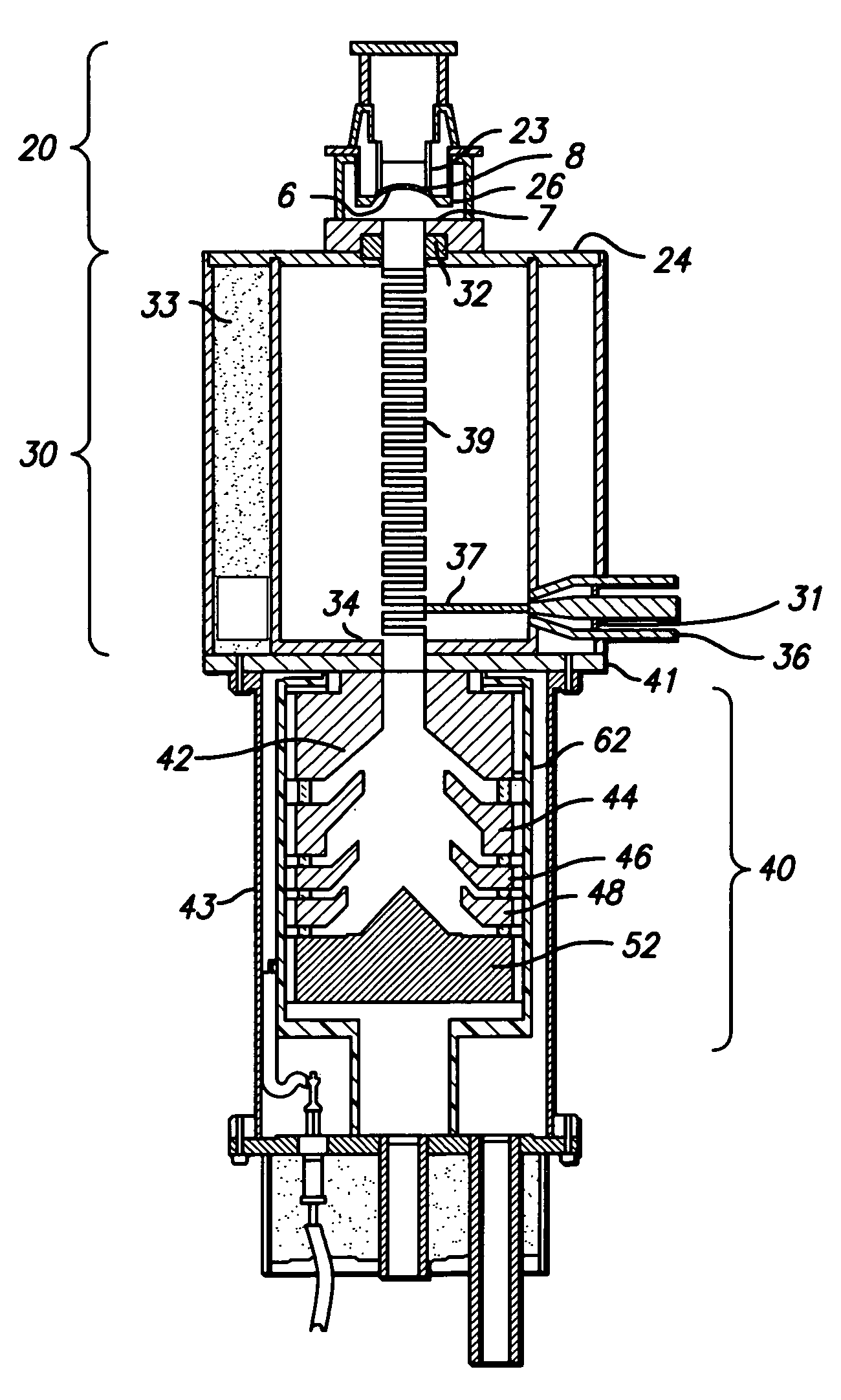
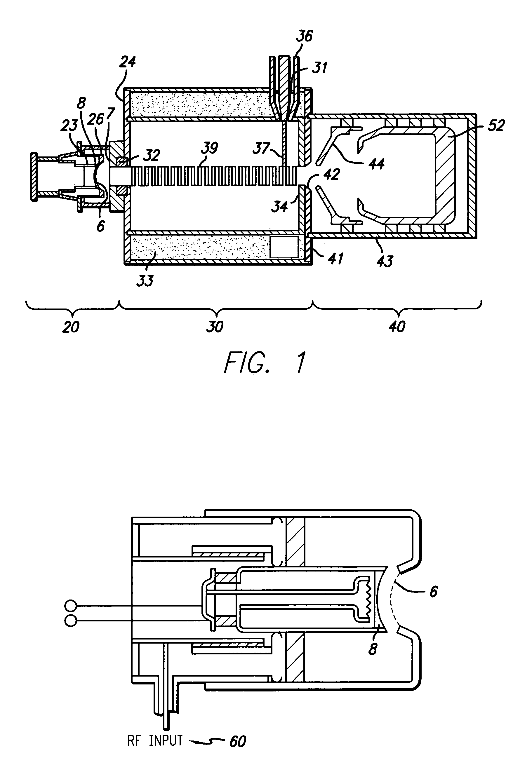
[0030]FIG. 1 illustrates an inductive output tube in accordance with an embodiment of the invention. The inductive output tube includes three major sections, including an electron gun 20, a tube body 30, and a collector 40. The electron gun 20 provides an axially directed electron beam that is density modulated by an RF signal. The electron gun 20 further includes a cathode 8 with a closely spaced control grid 6. The cathode 8 is disposed at the end of a cylindrical capsule 23 that includes...


PUM


Abstract

An inductive output tube (IOT) provides improved efficiency and larger bandwidth. In one embodiment, an IOT is provided with an electron gun that generates an electron beam, a tube body, a collector for collecting the electron beam, and an extended-interaction output circuit. The electron beam travels through the tube body and the extended-interaction output circuit. The extended-interaction output circuit is located within the tube body. The extended-interaction output circuit comprises a short-circuited resonant structure. The extended-interaction output circuit is used for reducing undesired components of a radio frequency (RF) wave, increasing desired components of the RF wave, and slowing down the propagation of the RF wave. (That is the circuit increases the integral of the electric field along the path of the beam electrons while decreasing the stored energy associated with those fields.) The extended-interaction output circuit also provides the IOT with larger bandwidth operation. The collector may be a multi-stage depressed collector having voltages on the collector to result in a constant efficiency characteristic. The radio-frequency drive power to the tube is connected by means of a broadband impedance matching transformer, and the grid to cathode capacitance may be reduced by depressions in the surface of the cathode directly underneath the grid structure.

Description

BACKGROUND OF THE INVENTION[0001]1. Field of the Invention[0002]The present invention relates to linear beam devices, such as inductive output tubes, used for amplifying a radio frequency (RF) signal. More particularly, the invention relates to an inductive output tube having an extended-interaction output circuit and / or wide-band input circuit.[0003]2. Description of Related Art[0004]It is well known in the art to utilize a linear beam device, such as a klystron amplifier or traveling wave tube amplifier, to generate or amplify a radio frequency (RF) signal. These amplifiers generally include an electron emitting cathode and an anode spaced therefrom. The anode includes a central aperture; by applying a high voltage potential between the cathode and anode, electrons may be drawn from the cathode surface and directed into a high power electron beam that passes through the anode aperture. The electron beam may be directly modulated in density with a grid in front of a cathode as in a...

Claims


Application Information

Patent Timeline
Patent Type & Authority Patents(United States)
IPC IPC(8): H01J25/02H01J23/027H01J23/18H01J23/24H01J25/04
CPCH01J23/0275H01J25/04H01J23/24
Inventor SYMONS, ROBERT SPENCER
Owner L 3 COMM CORP
Why Eureka
Try Eureka